
Control Line: Racing
John Ballard 10102 Kimblewick Dr. Louisville, KY 40223
Mouse Racing
This month's photos focus on 1/4A Mouse Racing. One photo, taken at the Tree Town Modelaires' Memorial Day contest, shows junior contestant David Schuette being pitted by his dad, Jim. These little models are tricky to pit when you're using the spring starter on the engine, so you can see that both the inboard and outboard wings are being stabilized while the spring starter is being engaged and wound. A further advantage of stabilizing the plane in this manner is that the pilot can be assured the plane is not angled either towards or away from the center of the circle when it's released, thereby allowing a smooth takeoff.
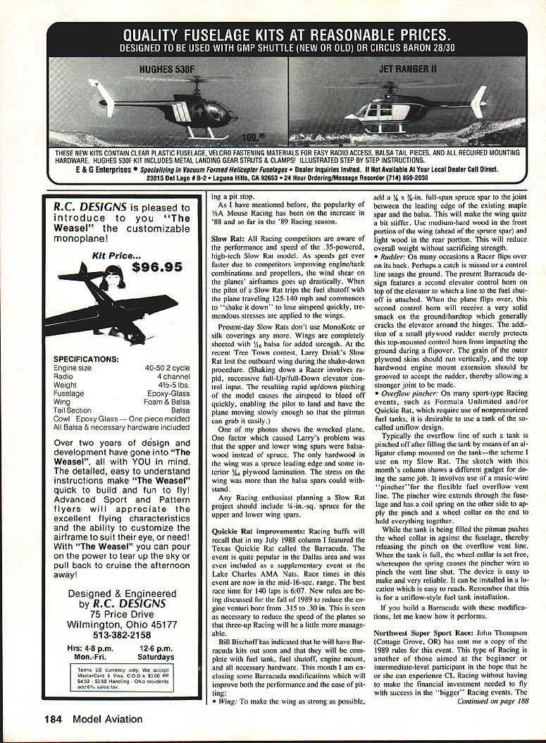
Another photo shows an unfortunate incident in Mouse Racing at the Northwest Regionals. In the Open event there was a severe line tangle. The pilots in this heat were Remi Dawson (Canada, dark-colored jacket), Bob Boling (El Cerrito, CA), and Tom Knoppi (Portland, OR). Remi's plane crashed, and the lines of the other two fliers remained tangled with his. Fuel shutoffs (not required for Mouse Racers) might have saved the day.
These photos highlight one of the deficiencies of Mouse Racers: they don't have fuel shutoffs. If the planes had been so equipped, all pilots could have shut down and saved their planes for another race.
Another of photographer Hawks' photos of the event shows two juniors doing an excellent job of piloting: Theresa Byerly and Wesley Mullins. The weather must have been chilly that day!
By not having fuel shutoffs, Mouse Racers are definitely subject to damage when line tangles—or some other unfortunate incident—occur. I have seen several cases where the engine has started backwards on a pit stop and the fact has not been apparent to the pilot. When the plane was released it moved backwards for a lap or two until either the engine quit or someone managed to capture it. Such embarrassing incidents could have been prevented had fuel shutoffs been installed.
As I have mentioned before, the popularity of 1/2A Mouse Racing increased in '88 and so far in the '89 Racing season.
Pit technique and gadgets
- It is extremely important for a competitor in multiple-pit racing events to have an overview of all activities occurring on his team. The pitman must be in the proper position to observe the other pilots as well as the pit area. He should be aware of the flying styles of all the other pilots. This helps eliminate confusion resulting from one crash or from a competitor's plane landing in the "home" pit area.
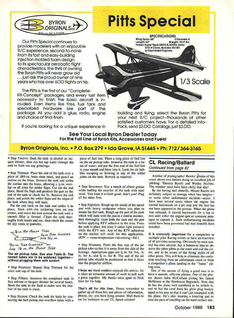
- Stabilize the plane when refueling. One photo shows John McCollum pitching his famous McMouse at the Northwest Regionals. Note that he has the plane well stabilized as he refuels it. He has the reel from his knee wrapped tightly around a strap so it can't get entangled with the plane. He's also wearing a kneeling pad to ease the pain of kneeling on the hard surface during repeated pit stops.
- Use a spring starter with a stabilized starter post. This ensures when the starter is engaged and wound the plane will not be tilted towards the inside or outside of the circle. A stabilized starter allows a smooth takeoff and less chance of a wing strike.
- Use a thumb guard or a strip of rubber glued to the inside finger of the glove to prevent cuts when handling the starter cord. If you can find a starter with a protective shield to keep the fingers away from the spring when it wraps around the shaft, use it.
- Carry a small mirror in the pit to allow the pitman to see the plane while it is being refueled, should the pilot be kneeling and unable to see. This little device can save headaches.
- Overflow pincher gadget: For uniflow-style suction-fed tanks, I use a music-wire "pincher" for the flexible rubber overflow line. The pincher wire extends through the fuselage and has a small spring on the other side to apply the pinch and a wheel collar on the end to hold everything together. While the tank is being filled the pitman pushes the wheel collar in against the fuselage, releasing the pinch and allowing fuel to flow into the tank. When the tank is full, the wheel collar is released and the spring causes the pincher wire to pinch the vent line shut. The device is easy to make, reliable, and can be installed where it's easy to reach.
Fuel tank fabrication — Steps
- Soak the tank in alcohol or lacquer thinner, then run hot tap water through the tank to flush out any grindings.
- Place the end of the tank over a piece of .005-in. brass shim stock, and pencil an outline on the brass. Remove the tank and scribe the outline into the brass, allowing a 1/8-in. overlap on all sides for solder flaps. Cut out the end piece. Bend the flaps and position the part on the end of the tank to check the fit. Remove the end piece, and pre-tin the solder flaps and the edges of the tank where they will mate.
Put the end back on the tank and solder in place. Start with the soldering iron on one corner, and move the iron around the tank until a smooth fillet is formed. Clean the tank thoroughly both inside and out, and then check the seams for any voids or pinholes.
Note: The air pickup tube — see also Table B. The nested tubes are to be soldered together — without plugging them with solder!
- Repeat Step 13 for the other end cap of the tank.
- Immerse the completed tank in flux solvent or lacquer thinner for several hours. Slosh the tank in the fluid to make sure the interior of the tank is clean.
- Check the tank for leaks by connecting the fuel pickup and overflow tubes with a piece of fuel line. Place a long piece of fuel line on the air pickup tube. Immerse the tank in a basin of water, and put the free end of the fuel line in your mouth and blow into it. Look for air bubbles escaping or forming at any of the solder joints on the tank. Rework as required.
- Use a bunch of elbow grease while buffing the exterior of the tank with steel wool. You want it to look good, don't you? Plug all the tubes first.
- Rough up the inside of the speed pan with heavy sandpaper where you plan to mount the fuel tank. Rough up the part of the tank which will mate with the pan in a similar manner, then thoroughly clean both the tank and the pan before applying RTV adhesive to the area. Press the tank in place and keep it under light pressure while the RTV sets. Any of the RTV adhesives on the market will work for this application. (RTV = room-temperature-vulcanizing.)
- Form the free end of the air pickup tube so that it is away from the side of the fuselage. Appropriate gaps are:
- 3/16 in. for .15 engines
- 1/8 in. for .09 engines
- 5/32 in. for .02 engines
The end of the air pickup tube should be positioned so it faces into the propeller airflow.
Slow Rat
All racing competitors are aware of the performance and speed of the .35-powered, high-tech Slow Rat model. As speeds increase due to improved engine/tank combinations and propellers, wind shear on the airframes goes up drastically. When the pilot of a Slow Rat trips the fuel shutoff with the plane traveling 125–140 mph and commences to "shake it down" to lose airspeed quickly, numerous stresses are applied to the wings.
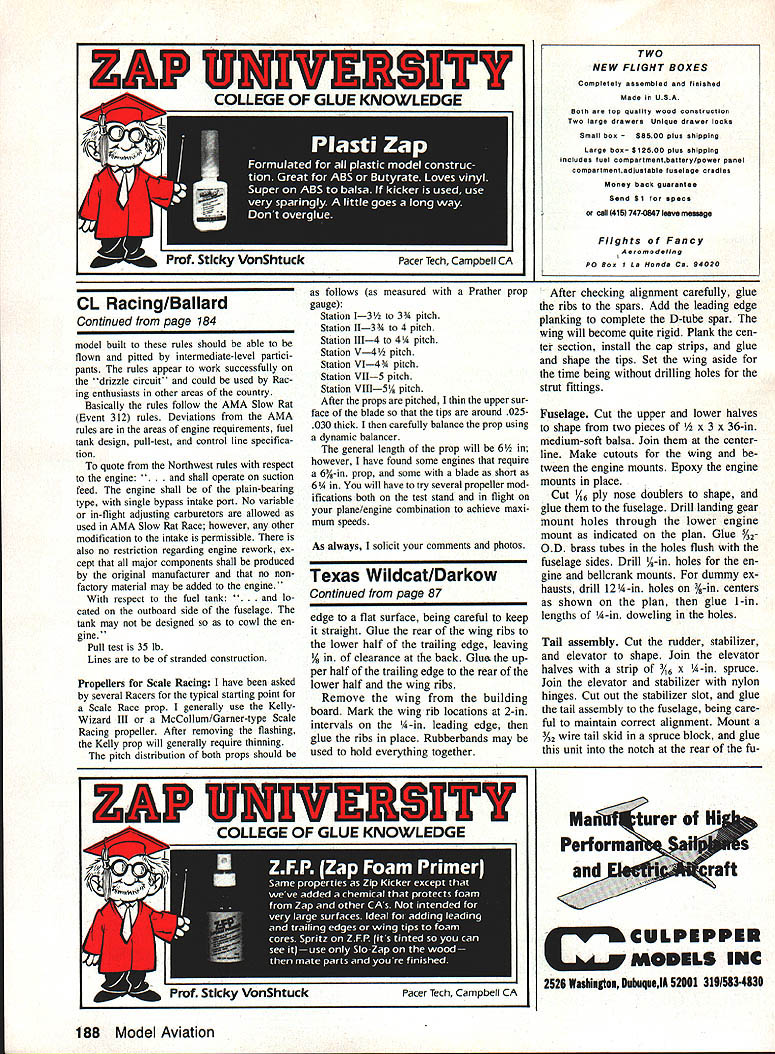
Present-day Slow Rats don't use MonoKote or silk coverings anymore. Wings are completely sheeted with 1/16 balsa for added strength. At the recent Tree Town contest, Larry Dziak's Slow Rat lost the outboard wing during the shake-down procedure. Shaking down a racer involves rapid, successive full-up/full-down elevator control input. The resulting rapid up/down pitching causes airspeed to bleed off quickly, enabling the pilot to land with the plane moving slowly enough for the pitman to grab it easily.
One factor causing Larry's problem was that the upper and lower wing spars were balsa instead of spruce. The only hardwood in the wing was a spruce leading edge and some pine 1/8" plywood lamination. The stress on the wing exceeded what the balsa spars could withstand.
Recommendation: Any racing enthusiast planning a Slow Rat project should include 1/4-in. spruce for the upper and lower wing spars.
Quickie Rat improvements (Barracuda)
Racing buffs will recall the Texas Quickie Rat called the Barracuda, featured in my July 1988 column. The design is huge in the Dallas area and was even included as a supplementary event at the Lake Charles AMA Nats. Race times in this area are now in the mid-16-second range. The best time for 140 laps is 6:07. New rules discussed for fall 1989 may reduce the engine vintage size from .315 to .30 in. to reduce plane speeds and make three-up racing more manageable.
Bill Bischoff has indicated he will have Barracuda kits soon, complete with fuel tank, fuel shutoff, engine mount, and all necessary hardware. Below are modifications to improve performance and ease of pitting:
- Wing: To make the wing as strong as possible, add a 1/8 x 3/4-in. full-span spruce spar at the joint between the leading edge of the existing maple spar and the balsa. This will stiffen the wing significantly. Use medium-hard wood in the front portion of the wing (ahead of the spruce spar) and light wood in the rear portion to reduce overall weight without sacrificing strength.
- Rudder: Racers sometimes flip over on their backs. The present Barracuda design features a second elevator control horn on the top of the elevator to which a line to the fuel shutoff is attached. When the plane flips over, this top-mounted control horn often receives the first crash loads and the elevator can crack around the hinges. Adding a small plywood rudder where it mounts to this top-mounted control horn will prevent it from impacting the ground during a flipover. The grain of the outer wing should run vertically, and the top hardwood mounting extension should be grooved to accept the rudder, allowing a stronger joint.
- Overflow pincher: See the gadget described previously for uniflow-style tanks. I use an alligator clamp on some models, but the music-wire pincher with a wheel collar and spring works well and can be mounted for easy access.
Northwest Super Sport Race
John Thompson (Cottage Grove, OR) sent a copy of the 1988 rules for this event. This type of racing is aimed at beginner or intermediate participants to allow experience in CL racing without the large financial investment required for the bigger events. The model built to these rules should be flyable and pitable by intermediate-level participants. The rules work successfully on the "drizzle circuit" and could be used by racing enthusiasts elsewhere.
The rules basically follow the AMA Slow Rat (Event 312) rules. Deviations are in engine requirements, fuel tank design, pull-test, and control line specification.
- Engine (quote): "... and shall operate on suction feed. The engine shall be of the plain-bearing type, with single bypass intake port. No variable or in-flight adjusting carburetors are allowed as used in AMA Slow Rat Race; however, any other modification to the intake is permissible. There is also no restriction regarding engine rework, except that all major components shall be produced by the original manufacturer and that no non-factory material may be added to the engine."
- Fuel tank: "... and located on the outboard side of the fuselage. The tank may not be designed so as to cowl the engine."
- Pull test: 35 lb.
- Lines: stranded construction.
Propellers for Scale Racing
Several racers have asked for a typical starting point for a Scale Racer prop. I generally use the Kelly-Wizard III or a McCollum/Garner-type Scale Racing propeller. After removing the flashing, the Kelly prop will generally require thinning. The pitch distribution for both props, measured with a Prather prop gauge, should be approximately:
- Station I — 3½ to 3¾ pitch
- Station II — 3¾ to 4 pitch
- Station III — 4 to 4¼ pitch
- Station IV — 4¼ pitch
- Station V — 4½ pitch
- Station VI — 4¾ pitch
- Station VII — 5 pitch
- Station VIII — 5½ pitch
After the props are pitched, thin the upper surface of the blade so the tips are around .025–.030 in. thick. Carefully balance the prop using a dynamic balancer.
General lengths: about 6¼ in.; some engines require 6⅜ in., others as short as 6⅛ in. Try several propeller modifications on the test stand and in flight to achieve maximum speeds for your plane/engine combination.
Closing
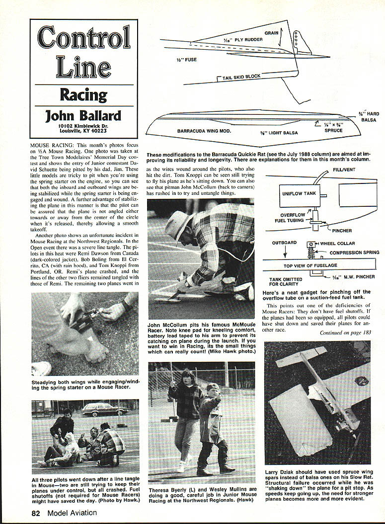
These modifications to the Barracuda Quickie Rat (see the July 1988 column) are aimed at improving reliability and longevity; explanations are provided above.
I hope my loyal readers enjoyed this article — it takes an immense amount of work to pull such a piece together. My thanks once again to Nick Sher for his help.
That's all for this time. Please remember to gather any bits and pieces of information, photos, etc., you have lying around. Mail them to me for inclusion in our CL Speed column!
As always, I solicit your comments and photos.
Transcribed from original scans by AI. Minor OCR errors may remain.

