
Control Line: Racing
John Ballard
10102 Kimbiewick Dr. Louisville, KY 40223
P.D.Q. Flying Clown
In my July column I mentioned that several Sport Racing enthusiasts had resurrected the P.D.Q. Flying Clown aircraft. In the late Fifties I built many Flying Clowns and used them for Combat. The Flying Clown had sturdy wing construction, and the wood included with the kits was first quality. The slightly smaller wing and shorter fuselage resulted in better maneuverability and better speed than the flying wings and other aircraft of the time. In addition, the spacing between the engine and leading edge of the wing was conducive to installing a 3-oz. profile tank for lengthy engine runs.
As the winter construction season came upon us, I received a flurry of letters concerning the availability of plans and/or kits for the long-extinct Flying Clown. I am happy to report that Joe Just, 709 Crescent, Sunnyside, WA 98944, has kits available, and he sold some 50 of them in just the last few months to be used in Sport Racing events. Joe's telephone number is 509/837-5983 for further information.
Lightweight epoxy construction system
I have recently received a sample of a new lightweight epoxy and some accompanying technical information from the Ciba-Geigy Plastics Division. The substance was used exclusively to construct an extremely lightweight full-size air racer with twin V-6 turbocharged engines, each producing 1,000 horsepower at 8,000 rpm. The plane's entire 25-ft. wing was fabricated from a sandwiched laminate consisting of a skin of carbon fiber impregnated with epoxy resin over a core of either structural foam or end-grain balsa wood.
After trying several different types of epoxy, I found that the new MYOS10 high-performance multifunctional resin and its companion hardener XB3075 were an excellent combination. The MYOS10 features high stability, excellent chemical resistance, but—most important of all—has extremely low viscosity with good storage stability and excellent cure rates with almost no heat distortion around the engine pod and other areas subject to higher temperatures. The hardener XB3075 has excellent resistance to all of our typical fuel compounds and, of course, forms a solventless, very low-odor resin. Along with low viscosity it can either be heat cured or used in a vacuum-bagging form. There is very little weight increase.
If you would like to try some of the material, you can order samples and technical literature from Ciba-Geigy Corporation, Plastics Division, Seven Skyline Drive, Hawthorne, NY 10532-2188. Let me know the results of your trial usage.
Scale Racers
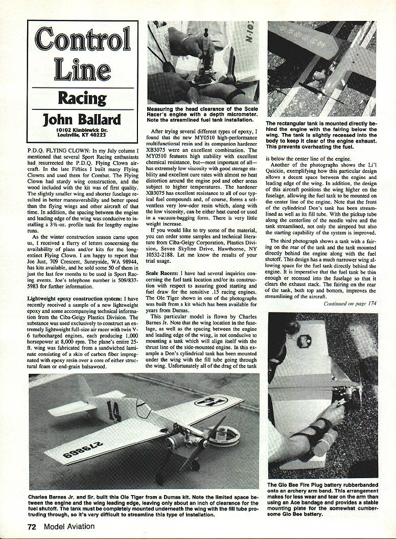
I have had several inquiries concerning the fuel tank location and/or its construction with respect to assuring good starting and fuel draw for the sensitive .15 racing engines. The Ole Tiger shown in one of the photographs was built from a kit which has been available for years from Dumas.
This particular model is flown by Charles Barnes Jr. Note that the wing location in the fuselage, as well as the spacing between the engine and leading edge of the wing, is not conducive to mounting a tank which will align itself with the thrust line of the side-mounted engine. In this example a Don's cylindrical tank has been mounted under the wing with the fill tube going through the wing. Unfortunately all of the drag of the tank is below the center line of the engine.
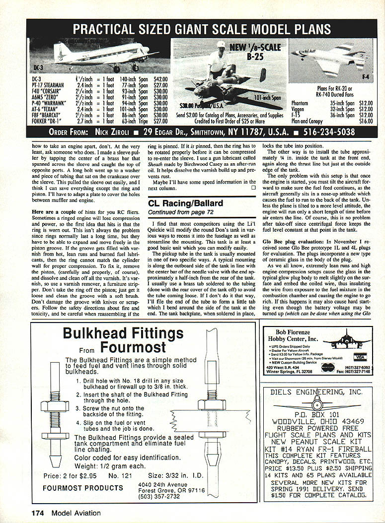
Another of the photographs shows the Lil' Quickie exemplifying a particular design which allows a decent space between the engine and leading edge of the wing. In addition, the design of this aircraft positions the wing higher on the fuselage and allows the fuel tank to be mounted on the center line of the engine. Note that the front cylindrical Don's tank has been streamlined as well as its fill tube. With the pickup tube along the centerline of the needle valve the tank is streamlined, and this helps both airspeed and starting capability of the system.
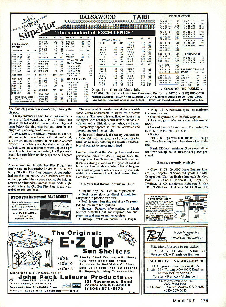
The third photograph shows a tank with a fairing on the rear of the tank and the tank mounted directly behind the engine. This fuel-shutoff design has a much narrower wing allowing space for the fuel tank directly behind the engine. It is imperative that the fuel tank be thin enough to be recessed in the fuselage to clear the exhaust stack. Fairing the rear of the tank both top and bottom improves the streamlining of the aircraft.
CL Racing / Ballard
I find that most competitors using the Lil' Quickie will modify the round Don's tank in various ways to recess it into the fuselage as well as streamline the mounting. This tank is at least a good basic unit which you can modify easily.
The pickup tube in the tank is usually mounted one of two specific ways. A typical mounting is along the outboard side of the tank in line with the center bar of the needle valve with the end approximately a half-inch from the rear of the tank. I usually use a brass tab soldered to the tubing (done with the rear cover of the tank off) to avoid getting the tubing loose. If I don't do it that way, I'll file the end of the tube to form a little tab which I bend around the side of the tank at the end. The tank backplate, when soldered in place, locks the tube into position.
The other way is to install the tube approximately 1/4 in. inside the tank at the front end, again along the thrust line but just at the outside edge of the tank. The only problem with this setup is that once the engine is started, you must tilt the aircraft forward to make sure the fuel feed continues, as the aircraft generally sits in a nose-up attitude which causes the fuel to run to the back of the tank. Unless the plane is tilted to a more level attitude, the engine will run only a short length of time before air enters the line. Of course, this is no problem after takeoff since centrifugal force keeps the fuel level constant at that point in the tank.
Glo Bee plug evaluation
In November I received some Glo Bee prototype 1L and 4L plugs for evaluation. The plugs incorporate a new type of ceramic glass in the body of the plug. As we all know, externally lean runs and high engine compression setups cause the glass in the typical glow plug body to melt slightly on the surface and embed the coiled wire, thus insulating the wire from exposure to the fuel mixture in the combustion chamber and causing the engine to go rich. If this happens it may also cause hard starting even though the battery voltage may be turned up, which can be done when using the Glo Bee plug.
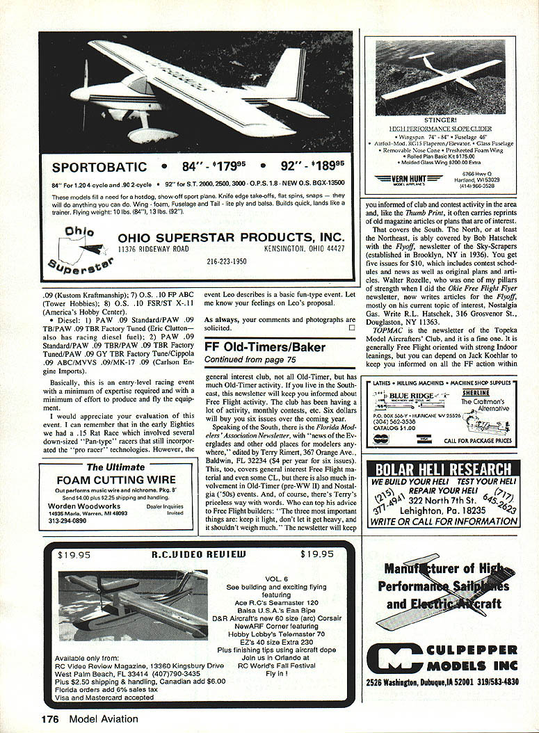
Arm mount for the Glo Bee Fire Plug
I recently saw an inexpensive holder for the rather bulky Glo Bee Fire Plug battery. A competitor had attached the battery to an archery arm band of the type which has a plate attached for holding arrows or other miscellaneous items. With slight modifications the Glo Bee Fire Plug is easily attached to this arm band.
The arm band fits neatly around the arm with three Velcro attachments to adjust for different sized arms. The battery is stabilized without using the typical Ace bandage which shuts off blood circulation and is difficult to use. Also, the battery is completely exposed so that the voltmeter and rheostat are easily accessible.
In the case I observed, the battery was used on a Slow Rat with the plug-in clip which can be used just as easily with finger contacts or another type of contact to the cylinder head.
Control Line Mini Rat Racing
I received some provisional rules for .09/.11-engine Mini Rat Racing from Leo Weitenberg. He indicates that there is a strong interest in this type of event in his locale. Leo has also included a list of the glow and diesel engines which are currently available within the aforementioned displacement limit.
CL Mini Rat Racing Provisional Rules
- Engine: Any .09-.11 cu. in. displacement.
- Fuel: Any glow or diesel formulation—competitor to provide own fuel.
- Fuel system: Fast fills and shut-offs permitted. No pressure feed systems.
- Exhaust: Factory, after-market, or Magic Muffler permitted but not required. No mini-pipes, megaphones or full tuned pipes.
- Fuselage: Profile—minimum 12 in. length.
- Wing: 18 in. minimum span—no minimum thickness or chord.
- Control system: Must be fully exposed.
- Landing gear: Minimum one wheel—must ROG.
- Racing: Control lines: .012 solid or .015 stranded; 52 ft. to 52 ft. 6 in.; pull test 10 lb.
- Heats: 60 laps with a minimum of one pit stop. Two heats required—best time taken to the final.
- Final: 120 laps—minimum 3 pit stops; all races flown two up; hot thumbs and hot gloves permitted.
Engines currently available
Glow:
- CS .09 ABC (Arco Engines Limited)
- Cipolla .09 Standard / Cipolla .09 ABC Competition (Carlson Engine Imports)
- Nova Rossi .09 (Andes Hobbies)
- Enya .09 TV / Enya .11 CX (Sheldon's Hobbies)
- Cox TD .09 (Sheldon's Hobbies)
- KK (Cox) TD
Basically, this is an entry-level racing event with a minimum of expertise required and with a minimum of effort to produce and fly the equipment.
I would appreciate your evaluation of this event. I can remember that in the early Eighties we had a .15 Rat Race which involved several down-sized "Pan-type" racers that still incorporated the "pro racer" technologies. However, the event Leo describes is a basic fun-type event. Let me know your feelings on Leo's proposal.
As always, your comments and photographs are solicited.
Transcribed from original scans by AI. Minor OCR errors may remain.

