
CONTROL LINE: RACING
Kenn Smith 521 Jansen Avenue, San Dimas, CA 91773
PROPELLER BALANCING (continued)
In the May issue we discussed prop balancers, pitch gauges, and the two types of balancing. Now we get into cleaning and preliminary shaping.
This may seem like a lot of trouble at first. However, the more times you properly prepare your racing propellers and see the advantage, the more you'll realize how important and beneficial the process is.
By cleaning I don't mean soap and water. Most high-performance props need major surgery to get them even close to the proper shape. A few high-performance prop manufacturers (APC and Bolly) provide props that are nearly ready to use and require only a bit of cleaning. These are very good props, but are a compromise product due to manufacturing restraints. Most high-performance specialty props are hand laid up in garage/shop facilities in one-prop-at-a-time molds made from masters perfected for specific events. They need a lot of cleanup.
The first (and only) step in cleaning up a prop is to remove all the flashing down to the mold line. The molding process leaves a distinct outline of the master prop — the mold line. Use a coarse file, rotary file, belt sander, disk sander, or other quick method to remove the excess flashing until you can just still make out the mold line.
This will get very messy. Do the work in a well-ventilated area and use a paint mask or respirator to avoid breathing carbon, glass, and resin dust.
Tools and supplies
- Medium-size files with fine cutting surfaces.
- A tapered rat-tail file (1/4-inch maximum diameter) for around the hub/blade joint.
- A half-round file (flat on one side and curved on the other) for shaping and thinning.
- Various grits (200 to 400) of wet-or-dry sandpaper.
- A small (6–12 inch) square of 1/4-inch plate glass.
- Very fine jeweler's files for shaping and finishing.
- A prop reamer (Fox makes a good one).
Finish the cleanup work using the fine files:
- Carefully file the leading and trailing edges of the blades to the mold line.
- Use the prop reamer to clean up the prop shaft hole.
- Round the hub/blade joint area so there is a smooth, rounded fillet between the hub and blade. Don’t remove too much material here—just remove excess resin.
- File the blade tips to proper length. Measure from the edge of the prop shaft hole and scribe a mark on the tip at the proper distance. Remember: when measuring from the edge of the hole, the mark should be at 1/2 the desired prop diameter minus 1/2 the hole diameter. File carefully to the marks and shape the tip as desired.
- Do not clip carbon-fiber or fiberglass props with scissors or side cutters; these tools can cause fine splits in the fibers that grow into large splits later.
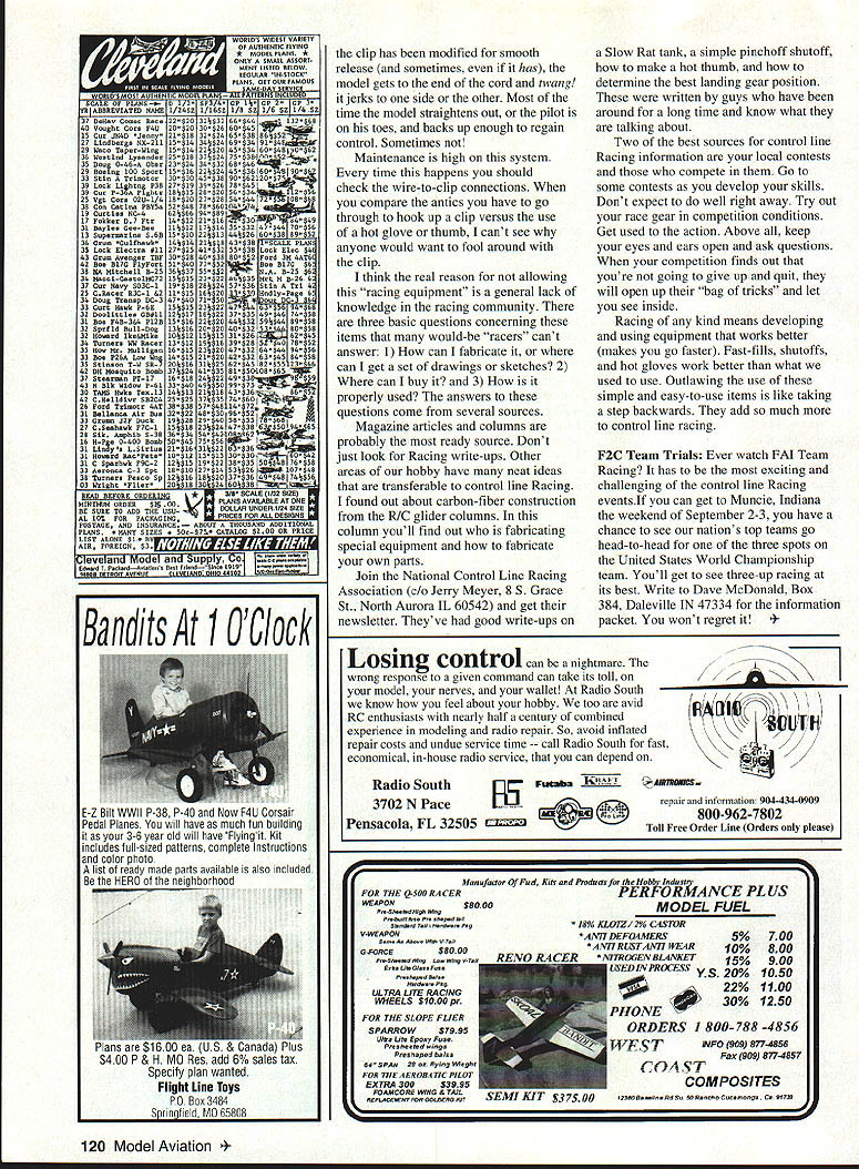
One of the most overlooked phases of propeller preparation is the hub base and spinner nut surface (front of the hub). They must be perpendicular to the prop shaft hole.
If the hub base is not smooth and perpendicular to the crankshaft (same as the prop shaft), two things can happen:
- If the prop is not perpendicular when viewed from the side (blades left and right), the blade tips will track different circles.
- If the hub base is not perpendicular when viewing the blade tip from the end, the blades will be at different pitch angles.
Either case will cause a dynamic imbalance. If the spinner nut surface is not smooth and perpendicular, tightening the nut will apply more pressure on one area and could cause hub failure.
Note: These conditions may not be repairable if the manufacturer produced a prop with the prop shaft hole out of alignment with the blades. A slight misalignment can sometimes be corrected by using a prop mount washer or spinner nut with a centering collar and enlarging the prop shaft hole to fit the collar.
Checking and correcting hub base and spinner nut surface You will need your pitch gauge (the checker), sandpaper, and plate glass (the correctors).
- Lay the plate glass on a smooth surface, put a piece of 220-grit sandpaper on the glass, add a couple drops of water on the paper, and smooth the prop hub base using a circular motion. Smooth the surface evenly and avoid adding any tilt.
- Wipe the prop clean and mount it on the pitch gauge holding fixture. Insert the fixture into a slot on the gauge. Hold the fixture down, rotate the prop until one blade is over the gauge surface, and measure from the surface to the blade tip. Rotate the next blade over the surface and measure again. Each blade tip should be the same distance from the gauge surface. Do not correct at this time.
- Move the prop holding fixture to a slot where you can check the pitch on one of the center stations. Check the pitch of both blades per the pitch gauge instructions. They should be the same.
Making corrections
- Using the sandpaper and plate glass, work down the high side of the hub base in small steps and with a circular motion. When the base is correct (blade tracking and pitches are equal), turn the prop over and repeat for the front surface.
- Match the pitch angles of the blades. With a small file, remove any bumps or imperfections from the bottom of each blade. Do not take material off the leading or trailing edges unless there are definite irregularities. Smooth and flatten the underside of the blade without changing the molded pitch angles.
- Using your pitch gauge, put lines across the bottoms of each blade at each pitch station (a fine felt-tip pen works well). Make a pitch chart with space to record start and finish pitch figures for each station of each blade; you may want space for interim readings. Check and record the pitch angle at each station.
Deciding target pitch You have five choices:
- Match the lowest-pitch blade to the highest.
- Match the highest-pitch blade to the lowest.
- Set both blades somewhere between the highest and lowest.
- Set both blades slightly higher in pitch than the highest.
- (Less common, and often limited by trailing-edge thickness) set both blades slightly lower than the lowest.
Pitching technique
- To decrease pitch, remove material from the trailing edge.
- To increase pitch, remove material from the leading edge.
- Keep checking the pitch until you reach the desired figures.
About tip pitch Props are usually set up with decreasing pitch from hub to tip. On thin, somewhat flexible racing props you might find an advantage in having the tips pitched 1/4"–1/2" higher than usual because at high speeds the tips tend to flatten out. Some stunt pilots also find more pulling power on high-revving pylon models when the engine is under load with props pitched higher at the tips.
Next time: blade shaping and matching.
FAST-FILLS, SHUTOFFS, HOT GLOVES, ETC.
Looking at local control line Racing rules around the country, many events prohibit fast-fill systems, fuel shutoffs, hot gloves, and pressure fuel systems. When I ask event organizers why, the answers are usually:
- "The equipment is too difficult to make."
- "The equipment is too difficult to use."
- "The equipment isn't available."
- "The event is a Beginner's event."
- "We don't want to bother with it."
These items are not difficult. The only secret in control line Racing is that there are no secrets. None of these items are any harder to fabricate than a new set of racing control lines or preparing a racing propeller. Building a light, strong airframe is much more difficult than making a hot glove or shutoff.
Reasons to allow (or require) special equipment
- Safety: Shutoffs should be required in all events except possibly Mouse racing. If there is a line tangle, or you get caught behind your model and can't catch up, you need to be able to shut the engine off.
- Engine preservation: If you go up to "get a needle" and go off-lean or off-setting, you can shut off rather than waste fuel or ruin an engine.
- Time savings: With a shutoff you can reset needles multiple times in the time it takes to make one setting change without a shutoff.
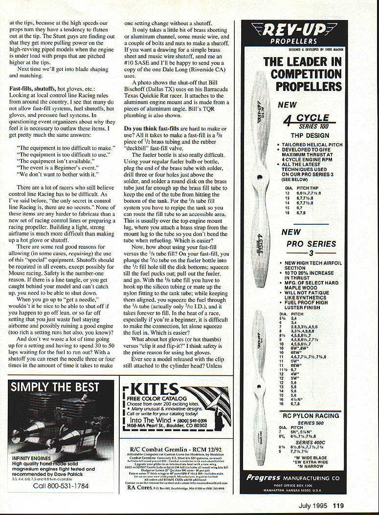
Making a simple shutoff It only takes a bit of brass sheeting or aluminum channel, some music wire, and a couple of bolts and nuts to make a shutoff. If you want a drawing for a simple brass-sheet-and-music-wire shutoff, send an #10 SASE and the author will send a copy of the one Dale Long (Riverside, CA) uses.
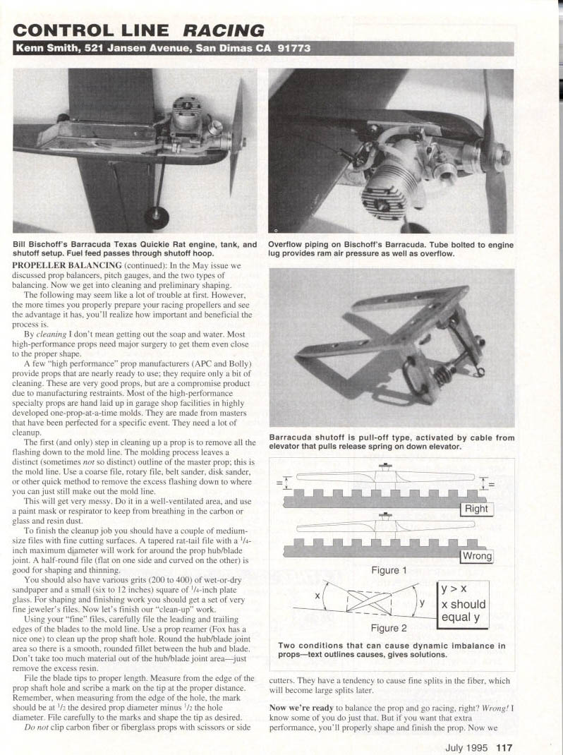
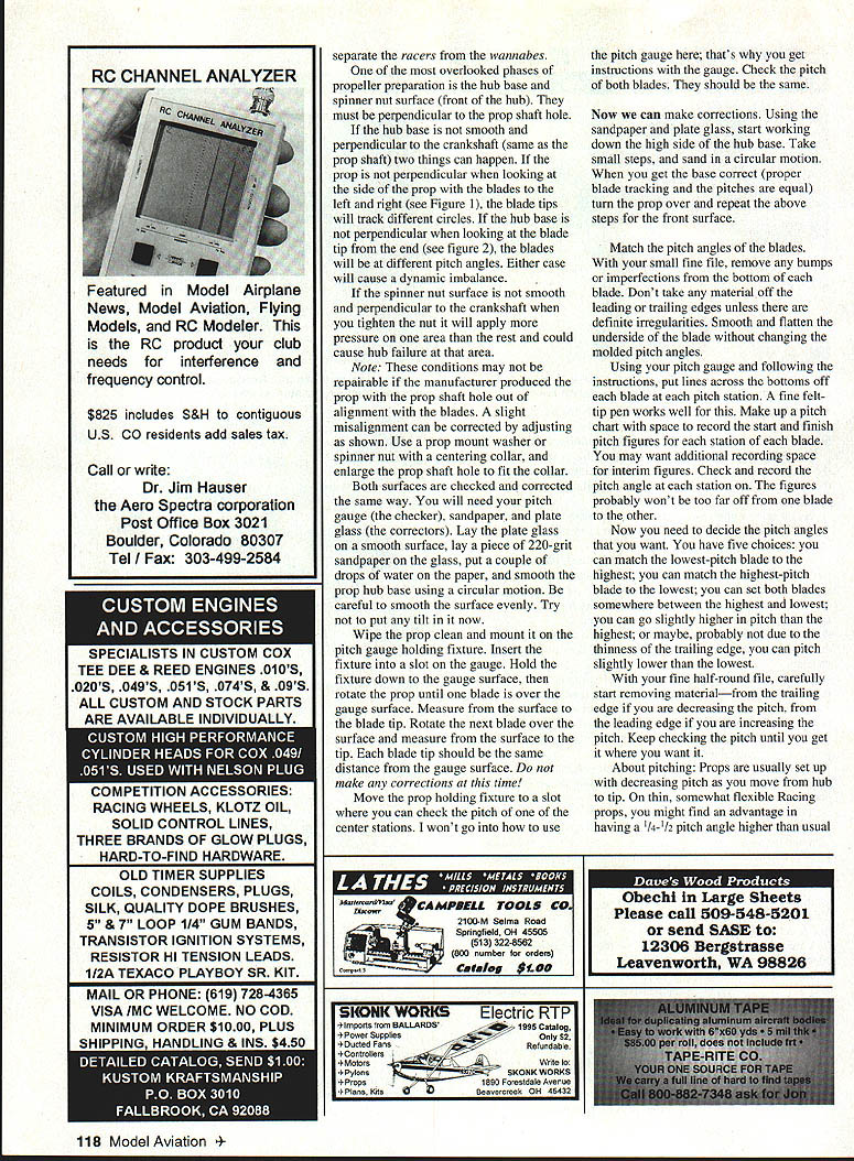
Example shutoff photo A shutoff used by Bill Bischoff (Dallas, TX) on his Barracuda Texas Quickie Rat racer attaches to the aluminum engine mount and is made from a piece of aluminum angle. (Photo originally accompanied the article.)
Fast-fill construction and fueller bottle
- All it takes to make a fast-fill is a 5/8" piece of 1/2" brass tubing and a rubber "duckbill" fast-fill valve.
- The fueller bottle is easy: plug the end of the brass tube with solder, drill three or four holes just above the solder, and solder a round disk on the brass tube far enough up to keep the end from hitting the bottom of the tank.
- For the 1/8" tube fill system you must reroute the tank so the fill tube is accessible, usually over the top engine mount lug. Attach a brass strap from the mount lug to the tube so you don't bend the tube when refueling.
Using fast-fill vs 1/8" tube fill
- Fast-fill: plunge the fueller tube into the 1/2" fill hole until the disk bottoms, squeeze the fuel, pull out the fueller, and go.
- 1/8" tube fill: hook up silicone tubing or mate a nylon fitting to the tank tube, keep them aligned, and squeeze fuel through the small ID (often 3/32"). It takes much longer and is harder to make the connection under race conditions.
Hot gloves (or thumbs) vs clip-and-flip
- Safety is the prime reason for using gloves. When a clip reaches the end of the cord it can suddenly release and the model can twang or jerk to one side, sometimes causing loss of control. Maintenance on clips is high — check wire-to-clip connections every time a twang occurs.
- Hot gloves/thumbs reduce the antics of clips and increase safety and reliability.
Why restrictions exist Often restrictions come from a lack of knowledge in the racing community. Three basic questions many would-be racers can't answer are:
- How can I fabricate it, or where can I get drawings or sketches?
- Where can I buy it?
- How is it properly used?
Sources of information
- Magazine articles and columns (not just Racing write-ups) often have transferable ideas. For example, carbon-fiber construction ideas came from R/C glider columns.
- Join the National Control Line Racing Association (c/o Jerry Meyer, 8 S. Grace St., North Aurora, IL 60542) and get their newsletter; they have good write-ups on tanks, shutoffs, hot thumbs, and more.
- Local contests and competitors are excellent resources. Attend contests, try your equipment in competition conditions, watch, ask questions, and learn from experienced racers.
Racing means developing and using equipment that makes you go faster. Fast-fills, shutoffs, and hot gloves work better than older methods. Outlawing simple, easy-to-use items is like taking a step backwards — they add a lot to control line racing.
F2C TEAM TRIALS
Ever watch FAI Team Racing? It's one of the most exciting and challenging control line Racing events. If you can get to Muncie, Indiana the weekend of September 2–3, you'll have a chance to see our nation's top teams go head-to-head for one of three spots on the United States World Championship team. You'll get to see three-up racing at its best. Write to Dave McDonald, Box 384, Dellville, IN 47334 for the information packet. You won't regret it!
Transcribed from original scans by AI. Minor OCR errors may remain.

