
Control Line: Scale
Mike Stott
WELL, THE FLYING season is starting here for most of us. That means dusting off the old Scale models or worrying about test flying that model you have spent all winter building. I hope the ideas in this column will help you to get off to a better and more enthusiastic start.
You may wonder how the Scale models that fly in competition get all the different options to operate at the proper time when they are flying and sometimes under very adverse conditions. The methods illustrated here may give you a better understanding or at least offer some suggestions on operating the multiple control systems.
Sturdi-Built Model Mfg. has a flight control system better known as the J-Roberts Three Line Unit. It is available in two different bellcrank units. The only difference in these two units is in the assembly of the bellcrank components to facilitate the easiest mounting in all types of models. The upright unit mounts on the top of the bellcrank floor while the suspended unit mounts on the bottom side of the floor. If you use an upright bellcrank and find that you are getting high throttle when you should be getting low throttle you can use a suspended bellcrank instead of the upright version which will give you the correct throttle movements. Both bellcranks are interchangeable to achieve the correct throttle movements you need.
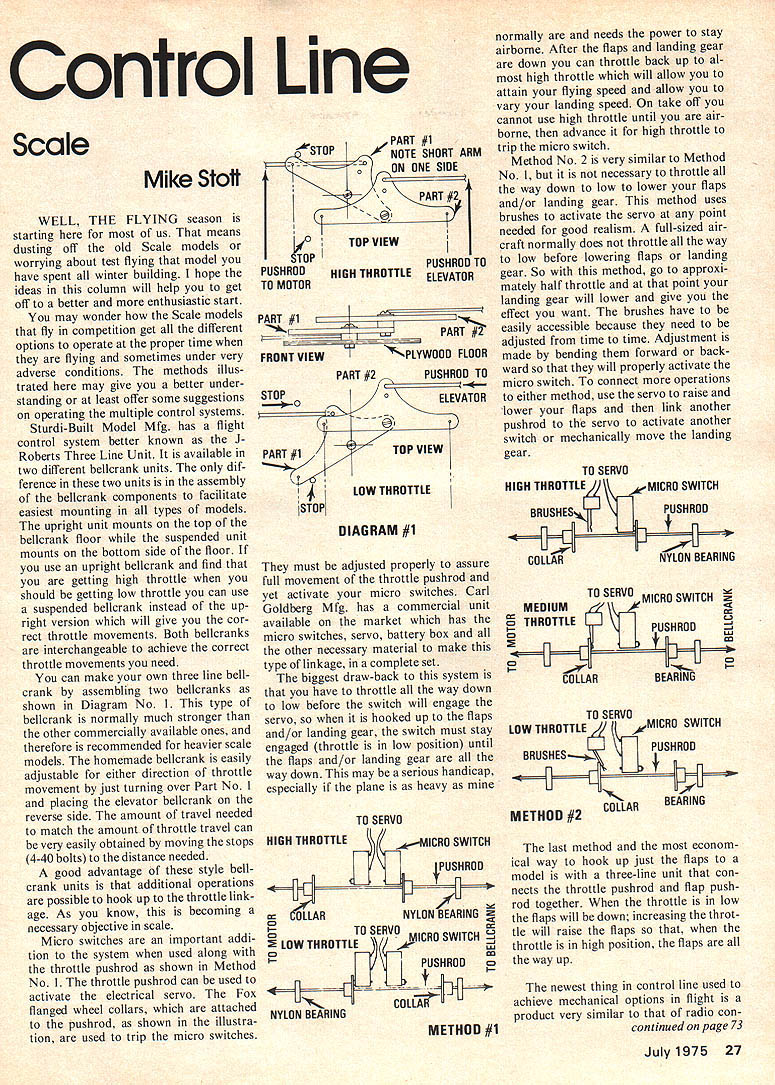
You can make your own three line bellcrank by assembling two bellcranks as shown in Diagram No. 1. This type of bellcrank is normally much stronger than the other commercially available ones and therefore is recommended for heavier scale models. The homemade bellcrank is easily adjustable for either direction of throttle movement by just turning over Part No. 1 and placing the elevator bellcrank on the reverse side. The amount of throttle travel can be very easily obtained by moving the stops (4-40 bolts) to the distance needed.
A good advantage of these style bellcrank units is that additional operations are possible to hook up to the throttle linkage. As you know, this is becoming a necessary objective in scale.
Micro switches are an important addition to the system when used along with the throttle pushrod as shown in Method No. 1. The throttle pushrod can be used to activate the electrical servo. The Fox flanged wheel collars, which are attached to the pushrod, as shown in the illustration, are used to trip the micro switches.
They must be adjusted properly to assure full movement of the throttle pushrod and yet activate your micro switches. Carl Goldberg Mfg. has a commercial unit available on the market which has the micro switches, servo, battery box and all the other necessary material to make this type of linkage, in a complete set.
The biggest draw-back to this system is that you have to throttle all the way down to low before the switch will engage the servo, so when it is hooked up to the flaps and/or landing gear, the switch must stay engaged (throttle is in low position) until the flaps and/or landing gear are all the way down. This may be a serious handicap, especially if the plane is as heavy as mine normally are and needs the power to stay airborne. After the flaps and landing gear are down you can throttle back up to almost high throttle which will allow you to attain your flying speed and allow you to vary your landing speed. On takeoff you cannot use high throttle until you are airborne, then advance it for high throttle to trip the micro switch.
Method No. 2 is very similar to Method No. 1, but it is not necessary to throttle all the way down to low to lower your flaps and/or landing gear. This method uses brushes to activate the servo at any point needed for good realism. A full-sized aircraft normally does not throttle all the way down to low before lowering flaps or landing gear. So with this method, go to approximately half throttle and the landing gear will lower and give you the effect you want. The brushes have to be easily accessible because they need to be adjusted from time to time. Adjustment is made by bending them forward or backward so that they will properly activate the micro switch.
To connect more operations to either method, use the servo to raise and lower your flaps and then link another pushrod to the servo to activate another switch or mechanically move the landing gear.
The last method and the most economical way to hook up just the flaps to a model is with a three-line unit that connects the throttle pushrod and flap pushrod together. When the throttle is in low the flaps will be down; increasing the throttle will raise the flaps so that, when the throttle is in high position, the flaps are all the way up.
The newest thing in control line used to achieve mechanical options in flight is a product very similar to that of radio control.
Control Line: Scale
The C/L Electrical Control System uses only two insulated lines, through which a coded signal is sent to a decoder, in the model, which operates servos to accomplish the desired operations. The system has up to six servos that can be used for many options in flight. They are all independent of each other and all can be activated at the same time or just one at a time. An example of this is the twin-engine Tigercat, which had individual throttle, flaps, retractable landing gear, operating landing gear doors and a tank drop. The controls are proportional so if you only want your flaps half way down just move the control lever half of the way down. To obtain more information on this system, write to me at this address: 118 E. Wheeler Ave., North Mankato, Minn. 56001.
As your columnist on Control Line Scale, I need your help with new and better ideas of building, detailing and controlling scale models. Please write to me at the address given earlier in this column with any ideas you would like to share.
Transcribed from original scans by AI. Minor OCR errors may remain.

