
Control Line: Scale
Bill Boss
INSTRUMENTS AND PLACARDS
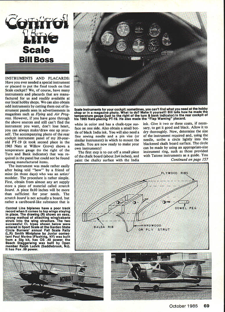
Have you ever needed a special instrument or placard to put the final touch on a Scale cockpit? Instrument placards are manufactured and are readily available from local hobby shops. You can also obtain odd instruments by cutting out instrument panels seen in advertisements and magazines such as Flying and Air Progress. However, if you have gone through the above sources and still can't find the instrument you want, don't lose heart — you can always make or draw one up yourself.
The rear cockpit instrument panel of a 20-year-old PT-19 that took second place in the 1965 Nats at Willow Grove shows a temperature gauge at the right. A Turn and Bank indicator required for the panel could not be found among manufactured items; the instrument was made rather easily after being shown the procedure by a friend who is an artist/modeler. The procedure is simple and uses common art supplies.
Materials
- Scratchboard (an 8 x 10 in. piece is sufficient)
- Black India ink (small bottle)
- Fine sewing needle and pin vise (or similar mount)
- Appropriate-size instrument rings (e.g., Tatone)
- X-Acto knife, razor blade, or scissors
- Jeweler’s loupe or other high-powered magnifier
Procedure
- Cut a small piece of scratchboard about 2 x 4 inches.
- Paint the chalky surface with India ink. Give two or three coats as necessary to get it uniformly black. Allow to dry thoroughly.
- Determine the required instrument size. Using the needle mounted in the pin vise, lightly scribe a circle on the blackened surface. An instrument ring makes a good guide.
- Within the scribed circle, continue to scratch the chalk surface at the appropriate places to create the instrument face. The ink will be scratched off, leaving white lines and markings.
- Use a magnifier while scribing small numbers and letters. Expect practice to improve results.
- When satisfied, carefully cut out the instrument and mount it in its instrument ring.
Cockpit placards can be made the same way. Note that the flap warning placard in the accompanying photo was made using this method.
BIPLANE WING-STRUT REINFORCEMENT (Preventing Upper-Wing Shear)
Problem: Over the years many biplanes have suffered upper-wing shearing during maneuvers such as wingovers and loops. Extreme lifting loads on the wings and connecting struts can cause catastrophic failure.
Example: At the 1980 Nats, Pete Bianchini’s Liberty Sport lost a lower wire at the top of a loop; the resulting failure destroyed the model. Pete rebuilt another Liberty Sport with minor modifications to the upper-wing installation using the reinforcement method described below.
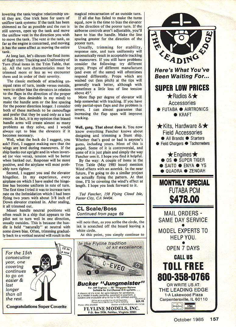
Reinforcement method (rib-sandwich and pegged struts)
- Make a set of ribs for each strut location using a wing rib from the area as a pattern:
- Use two ply ribs and one balsa rib (sandwich style).
- Ply thickness can range from 1/32 in. to 1/8 in., depending on model size and weight.
- Cut the balsa rib to the thickness of the wing strut and notch it for strut acceptance.
- Glue the ribs together in sandwich fashion so the center balsa rib is notched for the strut.
- Place the hardwood wing struts into the notches and drill holes through the assembly so the hole passes through the inserted portion of the strut.
- Size the hole to match the dowel peg selected. Example: for struts 3/8 in. or 1/2 in. wide, use 1/16 in. or 3/32 in. dowel pegs; for large single struts (as on the Beechcraft), use 1/8 in. dowel or larger.
- Fit and drill all struts, then install the newly made ribs in their proper wing locations.
- During final assembly, glue and pin the struts in place on both the upper and lower wing assemblies.
Result: A stronger wing assembly that better withstands the forces of aerobatic maneuvers.
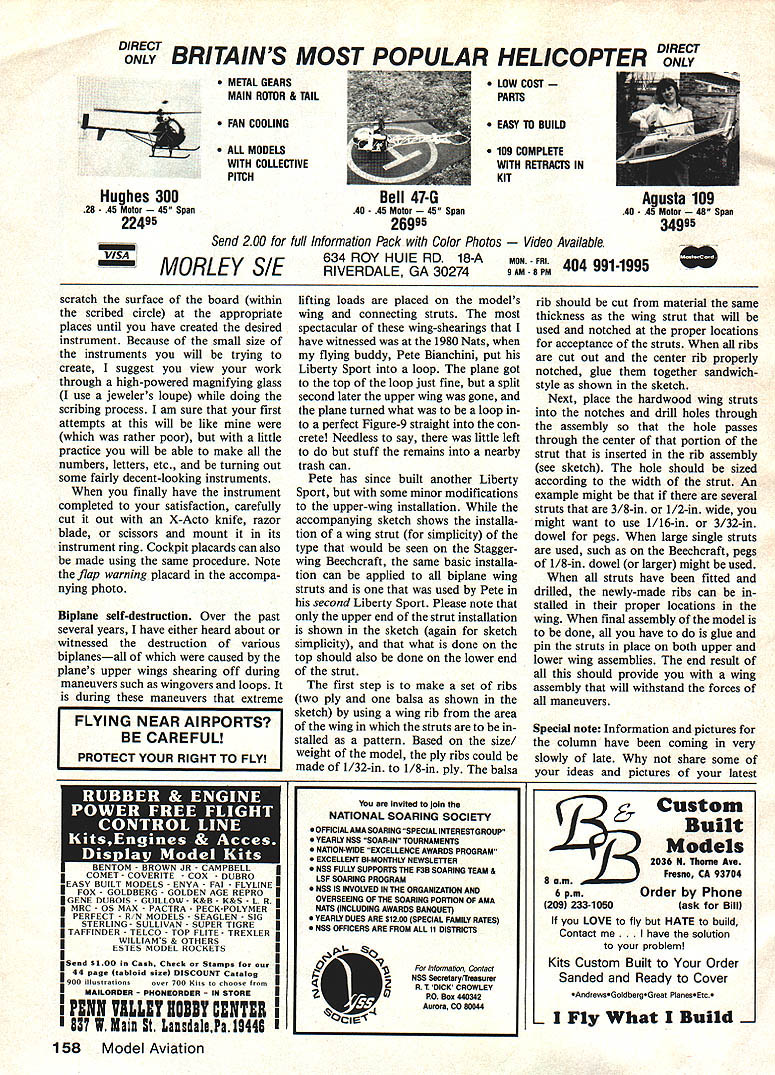
Examples of successful CL biplanes using careful construction and reinforcement:
- Smith Miniplane — Junior contestant Paul Marino (Flushing, NY), built from a Sig kit; OS .40 power.
- Beech Staggerwing — built by Ralph Ludwik (Saddlebrook, NJ); Fox .59 power.
TRIM: Tracking and Uniformity of Turn (Ted Fancher)
Final items of flight trim include Tracking and Uniformity of Turn. Trim each turn characteristic as encountered, in order of severity.
Recommended sequence and actions
- Ensure wings are level during maneuvers. If the ship banks differently upright versus inverted, tension and response will vary and the turn will likely be unequal.
- Seal the elevator hingeline. In the author’s experience, sealing the hingeline often produces uniform turn rates. Example: sealing cured a longstanding turn-rate problem on an Intimidator that had required 3/8 in. down elevator.
- Check handle neutral positions. Mis-set neutral often makes a ship appear not to turn well in one direction (usually outside turns) because the handle is held naturally with some down bias. Gradually trim the handle back to true vertical neutral — this can restore an outside turn.
- Bias the elevator only as a last resort. If all else fails, bias the elevator toward the poorer-turning direction. If airborne controls are not adjustable, bias the handle or increase line spacing for the poorer direction.
Additional tracking tips
- Switching props can affect tracking. Different props (even among those of the same pitch) may respond differently.
- Props washed out at the tips (less pitch) generally track better, though you may lose some line tension above 45 degrees.
- More flap per degree of elevator helps tracking. If you have partial-span flaps and tracking is poor, increasing flap span will usually improve tracking.
A note on tank/uniflow systems: If the tank has been shimmed as far as possible but the run is still uneven, open the tank and move the uniflow vent in the direction you wish to move the tank. The vent, as far as the engine is concerned, is the tank; moving it has the same effect as moving the entire tank.
Final comment from the author: Most of this guidance reflects long experience — some of it gospel, some controversial, and some personal preference. The author hopes it is helpful.
Ted Fancher 158 Flying Cloud Isle Foster City, CA 94404
SPECIAL NOTE
Information and pictures for the column have been coming in slowly. Share your ideas and photos of your latest projects with the Scale modeling world.
Send ideas and photos to: Bill Boss 77-06 269th St. New Hyde Park, NY 11040
Transcribed from original scans by AI. Minor OCR errors may remain.

