
Control Line: Scale
Bill Boss
Introduction
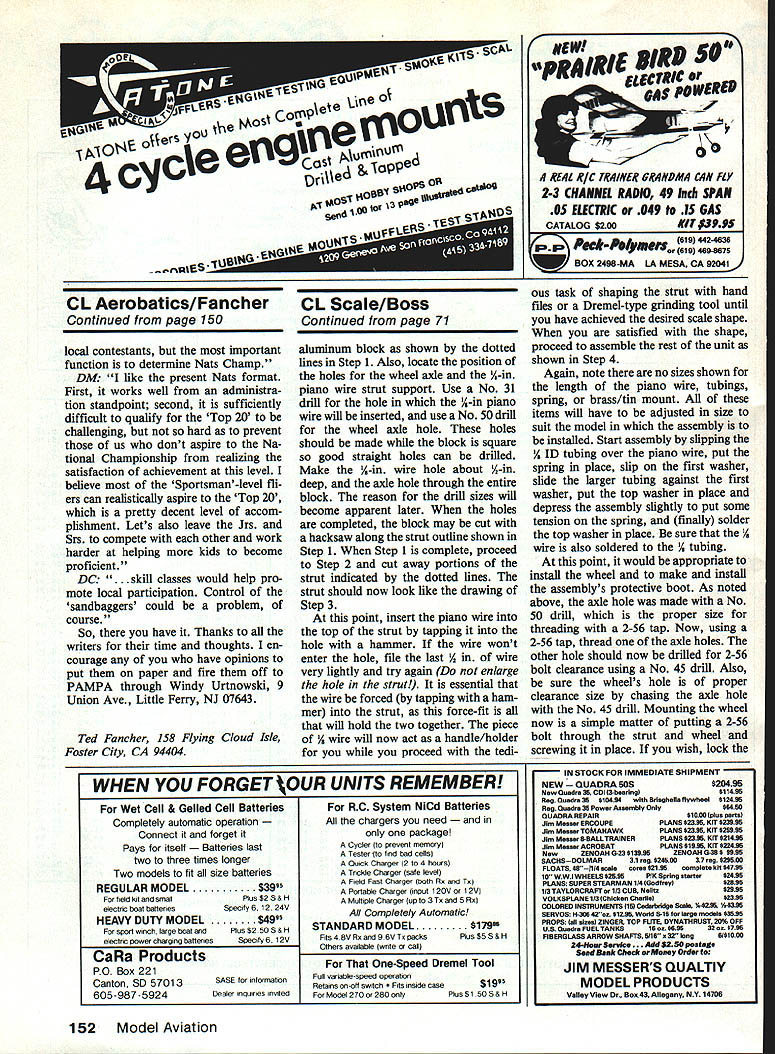
Scalelike tail wheel assemblies can be yours if you're willing to put some time and effort into making them. Dave Mullens (Seattle, WA) notes that while scale builders might expend great effort detailing most of their model, many do not pay enough attention to creating a scalelike tail wheel strut. Perhaps this is because it is such a small part of the overall plane, and most might feel that it won't be noticed if a super job is not done on it. We should make every effort to have all parts of our scale models look scale, and at Dave's suggestion we'll describe how to make a shock-absorbing, scalelike tail wheel strut.
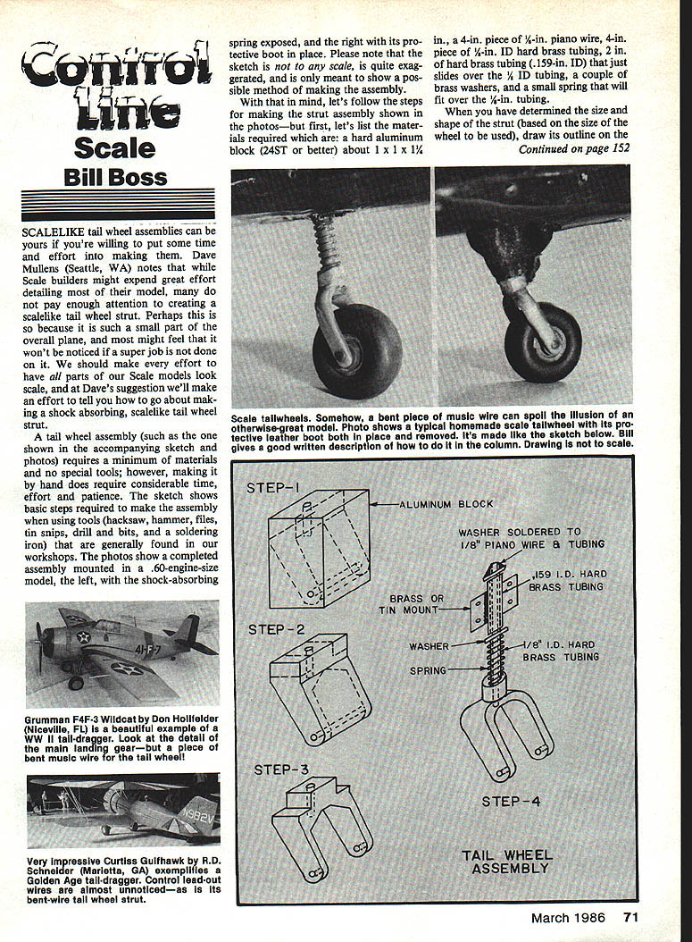
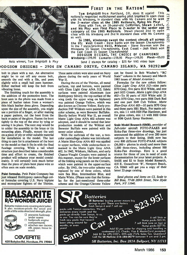
A tail wheel assembly (such as the one shown in the accompanying sketch and photos) requires a minimum of materials and no special tools; however, making it by hand does require considerable time, effort and patience. The sketch shows basic steps required to make the assembly when using tools (hacksaw, hammer, files, tin snips, drill and bits, and a soldering iron) that are generally found in our workshops. The photos show a completed assembly mounted in a .60-engine-size model: left, with the shock-absorbing spring exposed; right, with its protective boot in place. The sketch is not to scale and is exaggerated—it's meant only to show a possible method of making the assembly.
Materials
- A hard aluminum block (24ST or better) about 1 x 1 x 1 1/4 in.
- A 4-in. piece of 1/8-in. piano wire
- A 4-in. piece of 1/4-in. I.D. hard brass tubing
- 2 in. of hard brass tubing (.159-in. I.D.) that just slides over the 1/4-in. tubing
- A couple of brass washers
- A small spring that will fit over the 1/8-in. tubing
Note: No sizes are given for the length of the piano wire, tubings, spring, or brass washers—these must be adjusted to suit the model in which the assembly will be installed.
Making the Strut
- Draw the outline
- Determine the size and shape of the strut based on the wheel size.
- Draw the strut outline on the aluminum block and locate the wheel axle hole and the 1/8-in. piano wire strut-support hole.
- Drill the holes
- Use a No. 31 drill for the 1/8-in. piano wire hole (make this about 1/4 in. deep).
- Use a No. 50 drill for the wheel axle hole (drill through the entire block).
- Make these holes while the block is square so good, straight holes can be drilled.
- The reason for the drill sizes will become apparent later.
- Rough cut and shape
- Cut the block with a hacksaw along the strut outline.
- Cut away the portions indicated and file/shape until the strut resembles the intended profile.
- Fit the piano wire
- Insert the piano wire into the top hole by tapping it into place with a hammer. If the wire won't enter, file the last 1/2 in. of wire very lightly and try again. Do not enlarge the hole.
- The wire must be force-fit by tapping; this interference fit is what holds the two pieces together.
- The 1/8-in. wire will act as a handle/holder while you finish shaping the strut with files or a rotary grinding tool until you achieve the desired scale shape.
Assembly
- Slide components onto the piano wire
- Slip the 1/4-in. I.D. tubing over the piano wire.
- Put the spring in place.
- Slip on the first washer.
- Add outer tubing and top washer
- Slide the larger (.159-in. I.D.) tubing against the first washer.
- Put the top washer in place.
- Depress the assembly slightly to put tension on the spring.
- Secure and solder
- Solder the top washer in place.
- Be sure to solder the 1/8-in. piano wire to the 1/4-in. tubing.
- Install the wheel and protective boot
- Install the wheel axle and make and install the assembly's protective boot (see "Protective Boot and Finishing" below).
Drilling and Threading Axle Holes
- The axle hole drilled with a No. 50 drill is the proper size for threading with a 2-56 tap. Thread one of the axle holes with a 2-56 tap.
- The other axle hole should be drilled for 2-56 bolt clearance using a No. 45 drill.
- Also, ensure the wheel's hole is the proper clearance size by chasing it with the No. 45 drill.
- Mounting the wheel: put a 2-56 bolt through the strut and wheel and screw it into the threaded hole. Secure the bolt in place with a nut, or cut off any excess bolt, smooth the end with a file and peen slightly with a small ball-peen hammer. Either method will keep the bolt from vibrating loose.
Protective Boot and Finishing
- The boot shown in the photo was made from a piece of thin black leather taken from a woman's leather dress glove. Depending on the size of the assembly, you might use a portion of a finger or, after making a paper pattern, cut the boot from the back or palm of the glove.
- Fasten the boot tightly to the top of the strut by tying or sewing it in place.
- Solder the assembly to the brass or to the mounting plate.
- Mount the unit on a piece of plywood or other suitable material for installation in the model.
- Finally, attach the boot to the model so that it fits with the final fuselage covering.
While a tailwheel structure constructed as described takes considerable time and effort to create, the finished product will enhance your model considerably. It will certainly look much better than the plain bent piano wire so often seen on scale models.
Paint Formulas
Petit Paint Company has released Hobbypoxy camouflage color formulas covering U.S. Navy biplane and monoplane fighters of the 1930s. These same colors were also used on Navy planes during the early years of World War II.
Background:
- During the 1930s, all metal surfaces, top and bottom, were painted Gloss Light Gray ANA 512; fabric surfaces were painted Aluminum, Matte (see Hobbypoxy Silver); the top surface of the wing (only the upper wing on biplanes) was painted Orange Yellow (also known as Chrome Yellow). Early production F4F Wildcats and Brewster Buffaloes used this scheme.
- Shortly before World War II, an overall Matte Light Gray ANA 602 scheme was adopted; later production Wildcats and Brewster Buffaloes used this newer scheme.
- With the outbreak of the war, a two-color camouflage scheme was introduced: Matte Blue-Gray ANA 603 on upper surfaces and Matte Light Gray ANA 602 on undersurfaces. In 1942, Wildcats, Hellcats, and early Chance-Vought Corsairs used this scheme (except lower surfaces of folding wing panels on Corsairs, which were painted in the upper-surface colors).
- By 1943, the two-color scheme was replaced by a three-color scheme: Sea Blue, Intermediate Blue, and Matte White.
(Note: Formulas for the three-color scheme and the Orange/Chrome Yellow can be found in Bob Wischer's "RC Scale" column in the January and March 1985 issues of Model Aviation.)
Formulas:
- Gloss Light Gray ANA 512 — 9 parts H70 Gray, 5 parts H10 White, 1 part H55 Cream.
- Matte Light Gray ANA 602 — 70 parts H10 White, 21 parts H70 Gray, 2 parts H55 Dark Red, 1 part H49 Cub Yellow.
- Matte Blue-Gray ANA 603 — 10 parts H70 Gray, 3 parts H81 Black.
Mixing notes:
- For matte colors, mix 1:1 with H05 Flattener.
- For gloss colors, mix 1:1 with H02 Gloss or H06 Quick Spray Hardener.
Scale Model Research (SMR)
Scale Model Research (SMR), provider of full-color aircraft FOTO-PAAKS and Koku-Fan three-view drawings, has added over 200 new subjects to their listings. SMR now has over 800 different FOTO-PAAK subjects (36,000+ photos in stock) and more than 1,000 three-views, including almost 500 Koku-Fan drawings. They are a good source for drawings for scale documentation projects.
Request a catalog:
- Send a SASE and $2 to Scale Model Research, 418 E. Oceanfront "B", Newport Beach, CA 92661 for their latest 22-page catalog.
Send Items
Send photos and items on CL Scale to: Bill Ross 77-06 269th Street New Hyde Park, NY 11040
Transcribed from original scans by AI. Minor OCR errors may remain.

