
Control Line: Scale
By Bill Boss
Last month I covered some basics about a model's CG and where to place the bellcrank. I also talked about the importance of balancing the model before flight as a good, basic step toward avoiding disaster on the maiden flight. This month we continue with control-system basics by discussing possible methods of installing and supporting, as required, the bellcrank lead-outs.
As in last month's column, various questions from Steve Tift (Midland, TX) concerning a CL Scale model's control system form the basis for this month's discussion. Let's start with these questions: What is the purpose of the lead-out? Do the lead-outs have to be held or supported in any special way to keep the plane stable in flight? What are the rules regarding external, removable guides? Can lead-outs be hidden entirely to improve the model's appearance during static judging?
Purpose of the lead-out
The purpose of the lead-outs is simple: they provide the means by which we attach the model's flying lines to its bellcrank. The general placement of the lead-outs depends on the type of plane being modeled — high-wing, low-wing, mid-wing, biplane, etc. When installing lead-outs, the builder should make every effort to create a straight-line path from the bellcrank through the lead-outs and flying lines to the control handle. This yields the smoothest possible control operation and helps obtain a stable, level flight attitude when viewed head-on (both wingtips touching an imaginary horizontal line).
Why lead-outs must be supported
To obtain the desired flight attitude and control, the lead-outs must be held or supported at, or near, the inboard wing tip. If the lead-outs were not secured there, the model could yaw from side to side and fly in almost any attitude — which is not desirable. The supported inboard location helps keep the model stable and predictable in flight.
Common installation methods
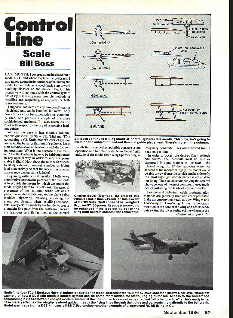
The sketch accompanying this column (not shown here) illustrates several commonly used lead-out installations. Below are the typical approaches for low-, mid-, high-wing models and biplanes.
Low- and mid-wing installations
Two general installation methods are commonly used:
- Low-Wing A: Bellcrank mounted in the wing core, lead-outs exit the lower surface of the wing near the inboard wing tip. This method works well when you want internal wing space for a bellcrank while keeping the fuselage free for cockpit detail (useful for Precision Scale models).
- Low-Wing B: Bellcrank mounted in the fuselage, lead-outs exit the fuselage above the wing's upper surface. Both Low-Wing A and B require lead-out guides at or near the wing tip to maintain the straight-line path from bellcrank to flying handle.
If the model has a wingspan of about 60 inches, experience suggests locating the lead-out guide as close as possible to the wing tip — roughly no more than six inches from the tip.
An alternative for low- and mid-wing installations is to put the entire control system inside the wing, despite a couple of degrees of dihedral. This internal routing eliminates the need for visible lead-out guides and holes and gives a much better appearance for static judging. I have used this successfully for many years on low-wing models without flight problems.
High-wing installations
High-wing models present their own considerations. The location of the bellcrank in the fuselage will determine how long the wing-tip lead-out guides must be so that the lead-outs are parallel to the bottom of the wing. Typical guides are formed piano wire attached to a rib near the tip of the wing. These can be fixed or made removable for better appearance during static judging.
Biplane installations
For biplanes, best results are achieved if the lead-out guide attached to the wing struts is located between one-third and one-half the vertical distance between the wings, measured from the upper surface of the lower wing. Lead-out guides for biplanes are generally made from plywood or sheet aluminum and attached to the struts between upper and lower wings. As with other types, these guides can be made removable.
Lead-out guide designs and removable options
Examples of common guide designs:
- Pre-formed and drilled piano wire with a nut to lock it in place; the mount can be brass or aluminum and attached to an appropriate rib. This can be used on low-, mid-, or high-wing models and made removable.
- A piece of 1/8-inch plywood affixed to a rib; it can be fixed or made removable with an appropriate mount.
- Piano wire bent and attached to a rib near the wing tip (high-wing).
- Plywood or sheet-aluminum guide attached to biplane struts.
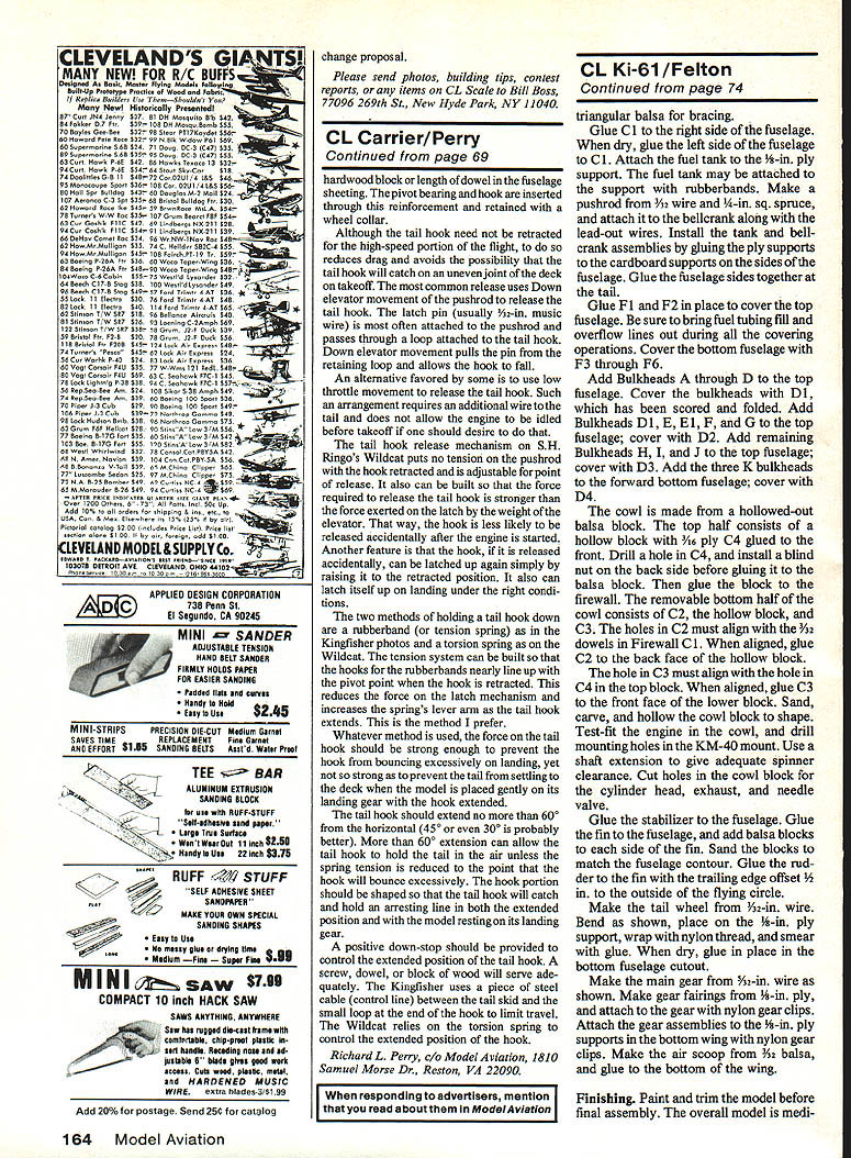
There is an ultimate alternative: design removable lead-out guides and a means of connecting the flying lines directly to the bellcrank. For example, Dave Copeman's North American T2J-1 Buckeye at the 1983 Nats used a removable cockpit module; after removing it, he connected the flying lines directly to the bellcrank via a removable guide at the wing tip. This allowed excellent static appearance.
With planning and extra effort, almost all CL Scale models can be made to have nonshowing control systems. WWII fighters and bombers can have hide-away line guides and removable wing panels for line connections. Biplanes and high-wing models can have removable line guides and fuselage panels behind which flexible lead-outs are routed and stored until ready for flight. The goal is to present a model for static judging without unsightly lead-out wires.
Rules and contest considerations
Be aware of rules differences between RC and CL: unlike RC Scale contests (where adding an antenna after static judging is allowed), current Control Line rules do not permit adding or changing anything on your model after static judging, except the propeller and spinner for flying. I interpret this to include removable line guides. While adding a line guide has rarely been contested, it is a possible source of trouble.
I plan to submit a rules-change proposal during the present rules-making cycle to clarify this area of concern.
Closing / Contact
Please send photos, building tips, contest reports, or any items on CL Scale to:
Bill Boss 77096 269th St. New Hyde Park, NY 11040
If you have questions about lead-out installation or removable guides, consider the installation method, the visibility for static judging, and the current contest rules before making changes.
Transcribed from original scans by AI. Minor OCR errors may remain.

