
Control Line: Scale
Bill Boss
Perseverance
If you don't succeed at first, try again. From the mail I received concerning my August and September columns on CG, balance, and lead-out positioning, it appears they were pretty well read. While most of the mail was supportive of the material presented, a couple of letters — one from Paul Burke (Palmdale, CA) and another from Tom Dixon (Atlanta, GA) — pointed out that I could have been more specific or technical in a couple areas.
After reviewing both the column and the letters, I realized that what I presented on a model's CG wasn't quite clear enough. Thanks, Paul and Tom, for your comments. I'll try to put some words together to provide a better picture.
Center of Gravity (CG)
I'll start by quoting Paul's definition of CG with respect to models; I believe it will put us on the right track.
"The CG (center of gravity) is a concept. It represents a position on the model that can be used to calculate the forces (such as gravity) which act on the structure. It has no 'always there' location. Take the motor out, the CG will move toward the tail. Take the tail off, and the CG moves toward the nose. All it represents is the theoretical spot where the weight of the structure is concentrated; and it's used for things like calculating forces or balancing. It's a point along the longitudinal axis where the aircraft balances in its current configuration, complete or not."
Paul goes on to indicate that the CG in most of our conventionally configured models is generally located at a point 25 to 30 percent of the wing chord (measured from the leading edge), and it is this point that is used to attain fore-and-aft balance of the model. Those who build from kits or plans will usually find that the designer has designated a CG point based on the model's structure, weight, designated engine size, etc.
Lead-outs and CG relationship
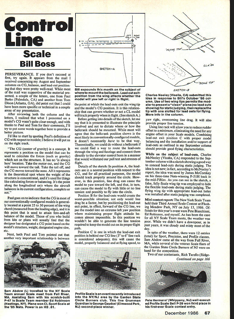
Both Paul and Tom pointed out that another very important relationship is between the point at which the lead-outs exit the wing tip and the model's CG position. It is this relationship that can govern whether or not a CL model will track properly when in flight. (See sketch-A.)
Before getting into details of the sketch, note that it is presented to illustrate the principle involved and not to dictate where or how the bellcrank should be mounted. While most will agree that the bellcrank position shown is the most likely in conventionally configured models, it doesn't necessarily have to be that way. Theoretically, you could mount a bellcrank and route the lead-outs through the wing and fuselage and connect them directly to the elevator control horn in a manner that will withstand the pull test and the stresses of flight.
Details of the sketch:
- Position A: The lead-outs are in a neutral position with respect to the CG, and for all practical purposes the model should track properly around the circle. However, in this position line drag can cause the model to yaw toward the left and, in turn, can cause the model to fly with little or no line tension and possibly to fly into the circle.
- Position B: This would create the worst possible situation. Not only would line drag be a factor, but by positioning the lead-out exit point, in effect, forward of the CG line, we put the model into an extreme left-yaw position where maintaining proper flight attitude becomes almost impossible. In this position we wouldn't be able to generate the line tension required to keep the model on its proper flight path.
- Position C: The lead-out exit position is behind our CG line (3° to 6° line rake is considered adequate); this will cause the model, properly balanced and at flying speed, to yaw right, overcoming line drag. It will also provide proper line tension.
Using line rake will also allow you to reduce rudder offset to a minimum, eliminating the need for any engine offset in your Scale models. Combining lead-out exit position C with proper model balancing and the installation and/or support of lead-outs as outlined in my September column should provide the model with good flying characteristics.
Concealing lead-outs for static judging
While on the subject of lead-outs, Charles McNeeley (Visalia, CA) responded to the September column with a sketch showing a good way to conceal lead-outs during static judging. The idea was used by James McCorskey on his three-time Nats-winning P-51H back in the mid-Fifties. As shown in the sketch, a false, full-scale wing tip was employed to hide the flexible lead-outs during static judging. The flying wing tip with appropriate lead-out holes was installed after static judging was completed.
Mini contest report
The New York Scale Team held their Third Annual Scale Contest at Flushing Meadow Park, NY, July 13, 1986. Officials for this year's event were Pete Bianchini, Ed Robinson, and myself. As has been the case for NY Scale Team meets, the weather was poor; while we didn't have the downpour of past years, it was cloudy and misty most of the day.
In spite of the weather, there were 12 entries (total) for Sport, Precision, and Profile classes. Sam Abdow came all the way from Fall River, MA, while several veteran Scale fliers from the Garden State Circle Burners of NJ were on hand for the competition.
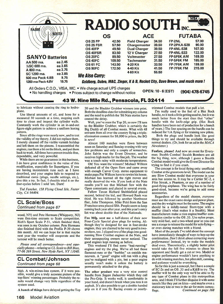
Two of our contestants, Rich Turello (Ridgewood, NY) and Pete Hermans (Whippany, NJ), were first-time entrants to Scale competition. Rich's Sport Scale P-51, which finished third, was seen in my October column. Pete Hermans also finished third with the Profile P-39 shown this month. All we can hope for is that maybe next year the weather will cooperate and the turnout will be much better.
Correspondence
Please send all correspondence — and especially photos — relating to CL Scale to: Bill Boss 77-06 269 Street New Hyde Park, NY 11040
Transcribed from original scans by AI. Minor OCR errors may remain.

