
Control Line: Scale
Bill Boss
Rocker-arm alternative to a bellcrank
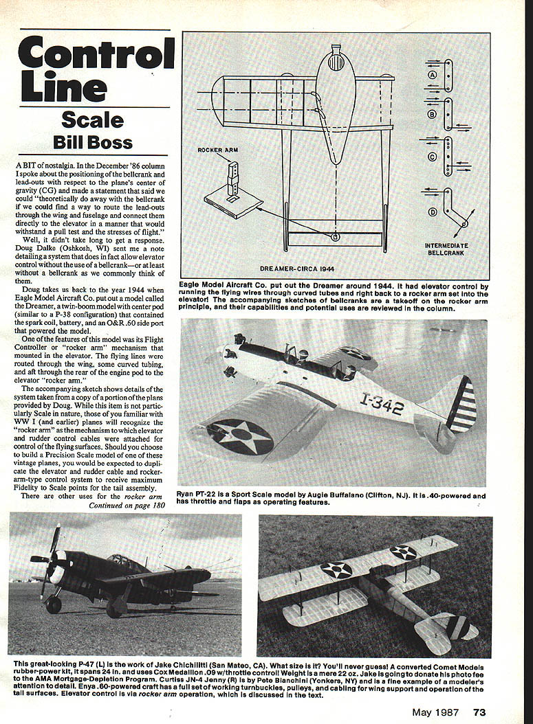
A bit of nostalgia. In the December 1986 column I discussed positioning the bellcrank and lead-outs relative to the plane's center of gravity (CG) and suggested we could "theoretically do away with the bellcrank if we could find a way to route the lead-outs through the wing and fuselage and connect them directly to the elevator in a manner that would withstand a pull test and the stresses of flight."
Doug Dalke (Oshkosh, WI) answered quickly with a historical example that does exactly that. He sent plans for the 1944 Eagle Model Aircraft Co. Dreamer, a twin-boom model with a center pod (similar to a P-38 configuration) housing the spark coil, battery, and an O&R .60 side-port engine. One feature was its Flight Controller or "rocker arm" mechanism mounted in the elevator. The flying lines were routed through the wing, through curved tubing, aft through the rear engine pod, and attached directly to the elevator rocker arm.
While not particularly Scale in modern terms, the rocker-arm mechanism is familiar to those who model WW I and earlier aircraft: elevator and rudder control cables attached to a rocker arm. If you build a precision scale model of these vintage designs, duplicating the cable-and-rocker-arm control system will earn maximum fidelity-to-scale points for the tail assembly.
The bellcrank principle for scale models
When I say "rocker arm principle" I mean the operation of what we normally call an intermediate bellcrank. The accompanying sketch (from Doug's plans) also illustrates a series of bellcranks, labeled A to D, to show various operations obtainable from this simple device. All the bellcranks shown share one function: they change the direction of motion of an output rod by pushing or pulling either of the pushrods. The direction of motion is represented by paired arrows, and although the sketches show the bellcranks vertically, they may be mounted vertically, horizontally, or at any angle to achieve the required motion.
- Bellcrank A
- Can be used to operate a bomb or external fuel-tank release mechanism.
- A vertical mounting under the main bellcrank lets the moving pushrod be run to either side of the fuselage, with the output rod running to a release mechanism mounted on the wing center section.
- In the sketches A is shown with control points equidistant from the center, so output travel is equal in both directions.
- Bellcrank B
- Commonly used to change pushrod direction in the engine compartment (for example, when the servo is in the fuselage and the throttle arm is on the engine).
- Allows routing when a direct straight run is not possible.
- Bellcrank C
- Similar operation to A and B but shown with a series of holes on each side of the center to permit selection of different amounts of pushrod travel.
- Useful where additional mechanical advantage or different travel is required (e.g., lowering flaps or opening cowl doors).
- Bellcrank D
- Generally used to change the angle of pushrod travel; available in 60°, 90°, and 120° versions.
Considerations:
- The length or height of an intermediate bellcrank depends on the operation and its location in the model.
- Control-surface loads and resultant stresses on the model’s control system must be considered. If insufficient actuating force is provided, airflow against a surface can prevent full operation. There is no simple universal formula for these flight stresses; experimentation is often the best approach. If anyone can provide specific formulas or data, I’d be glad to hear from them.
Making or buying bellcranks
You can make bellcranks from sheet aluminum (about 1/16 inch thick) from your scrap box. If you prefer not to make your own, hobby catalogs usually carry bellcranks (often nylon) that fit most needs. With a little imagination you can find or fabricate bellcranks for nearly any operation.
Notes and correspondence
- I received a note from "Big Art" Adamisin indicating he has finally satisfied himself that the modified OS .40 FP is a viable stunt power plant and is making them available for sale. Art is known for his lapped-piston OS engine modifications; his earlier modified .35s are collector's items today (except for those still flying after hundreds of flights). His modifications are extensive and not cheap. He is asking $130 per copy, including a custom muffler. Call him at (319) 521-9079 for details.
- For additional scale documentation: most Foto-Paaks include three-views that provide complete reference material in one package. For a new SMR listing of Foto-Paaks and three-view drawings, send a self-addressed envelope to:
- Scale Model Research, 2334 Ticonderoga, Costa Mesa, CA 92626.
- Correspondence:
- Please send all correspondence—and especially photos—relating to CL Scale to:
- Bill Boss, 77-06 269th St., New Hyde Park, NY 11040.
- Other contacts (from correspondence):
- Ted Fancher, 158 Flying Cloud Isle, Foster City, CA 94404.
Transcribed from original scans by AI. Minor OCR errors may remain.

