

Control Line: Scale
Bill Boss
History and basics
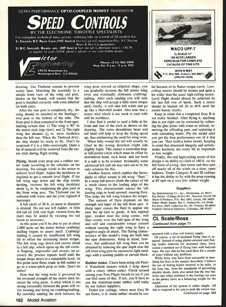
Electronic control systems for CL Scale models date back to the early 1970s. Mike Stott, a notable CL Scale competitor, is credited with originating the idea of passing electrical signals through a pair of insulated lines to operate servos in the model. At the 1973 Oshkosh Nationals Stott discussed the concept with Ken Wilson, a hobby dealer and EK Logitrol service technician. By 1974 both Stott and Mike Gretz had working systems and flew models equipped with this new electronic control at the 1974 World Championships in Lakehurst, NJ.
The basic arrangement uses the encoder section of a standard RC transmitter, a set of insulated control lines, and the decoder/servos from an RC receiver. A typical control box contained six trim-type slide controls, the encoder, and its power supply. Moving a slide control causes the encoder to generate an electrical-impulse signal that is passed down the insulated lines to a decoder in the aircraft; the decoder interprets the signal and drives the appropriate servo. Note: the signal is an electrical impulse on the lines — not a radio-frequency signal — and there is no radio transmitter/receiver involved. (Control Line rules — see "Control Line General", paragraph 2 — strictly prohibit RF signals for CL control.)
The lines used were plastic-coated steel fishing leader cable, .030 in. thickness (.043 in. overall with plastic covering), rated 120-lb test. A two-line system was chosen because all functions (including throttle) were performed from the control box; elevator control was retained as a mechanical function using the standard bellcrank.
Stott system and early manufacturing
Ken Wilson constructed the Stott system using EK Logitrol components and arranged for manufacture of the units. Because the CL Scale market in the U.S. was relatively small, sales were not brisk — it appears only three units were sold (to Bill Harney, Ed Rhoads, and Dan Osdoba). Several foreign modelers, however, adopted the system sooner; by the 1976 World Championships Scale teams from England, France, and Russia had incorporated the system in their models.
Later adoption in the U.S.
U.S. CL Scale interest in electronic line-control systems grew in the early 1980s. In 1983 Clancy Arnold flew a P-38 equipped with an electronic control system; I featured that model in my October 1984 column, which describes how one basic system works and the types of input control that can be used. Charles Bauer has also used and promoted electronic systems in several models since about 1984. Both Clancy and Charles have been involved in trying to market their systems and can provide information to interested modelers (see Contacts below).
Other modelers reported using electronic line-control systems include Dick Byron (Australia), Graves, and Steve Ashby. One of the barriers for some CL modelers has been cost; depending on the number and type of servos, a system can run roughly $200–$300.
Alternate approach: JR radio direct servo-coupling (Jeff Perez)
Jeff Perez used a different approach when flying his Piper Cherokee at recent FAI team trials. He used a Circus Hobbies JR radio that had a direct servo-test/coupling feature (a test patch cord and plug arrangement that directly drives servos without RF transmission). Perez substituted insulated control lines for the test patch cord and wore the transmitter box on his belt (he removed the frequency module from the transmitter to ensure no RF operation). If you are interested in this method, check with Circus Hobbies to confirm whether the direct-servo feature is available on current JR systems.
Flap relay system (Jerry Blaszczyk)
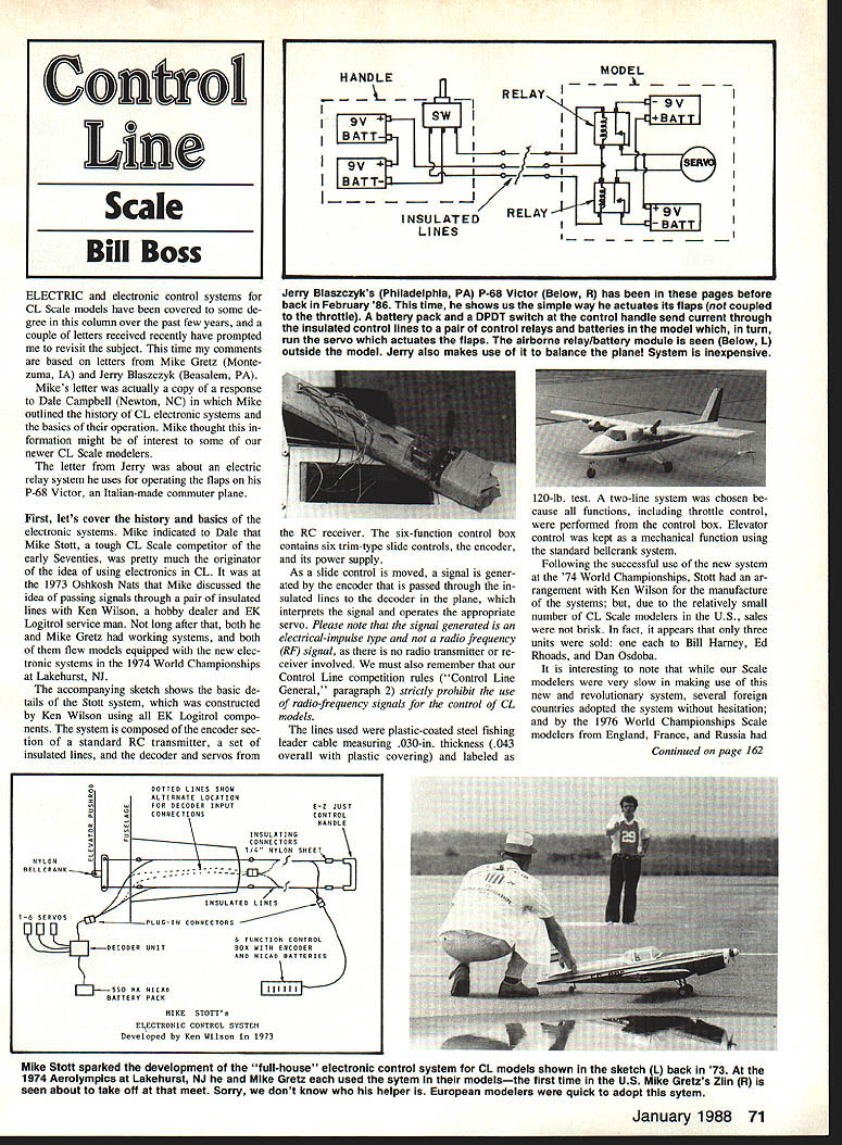
For a single operational feature (flaps), Jerry Blaszczyk of Philadelphia uses a simple, inexpensive electrical relay system for his Italian P-68 Victor. The system summary:
- Control: DPDT momentary switch mounted in a small chassis box (approx. 2-1/4 x 2-1/4 x 1-1/8 in.), which can be attached to the handle or strapped to a belt. Releasing the switch returns it to Off.
- Airframe: Two mini SPDT relays, an electric RC-type servo (one that can be driven in each direction), and a battery supply in the aircraft.
- Operation: The switch in the handle sends current through the insulated control lines to the airborne relays/battery module; the relays power the servo to move the flaps up or down. Releasing the handle cuts power and stops the servo.
Parts available from Radio Shack (as used by Jerry):
- Four 9-volt battery snap connectors — Part No. 270-325
- One DPDT momentary switch — Part No. 270-235
- Two mini-size SPDT relays — Part No. 275-004
- RC servo — model of your choice (must drive both directions)
Cost: This relay/battery/connector/control-box method is economical — roughly $20 for relays, batteries, connectors, and the control box — and is a practical interim solution unless/until competition rules prohibit such operation.
Contacts
- Clancy Arnold: 7536-C Ivywood Drive, Indianapolis, IN 46250
- Charles Bauer: 4944 N. Orange, Norridge, IL 60656
Acknowledgments
Thanks to Mike Gretz and Jerry Blaszczyk for their input to this column.
Transcribed from original scans by AI. Minor OCR errors may remain.

