
Control Line: Scale
Bill Boss 77-06 269th Street New Hyde Park, NY 11040
Introduction
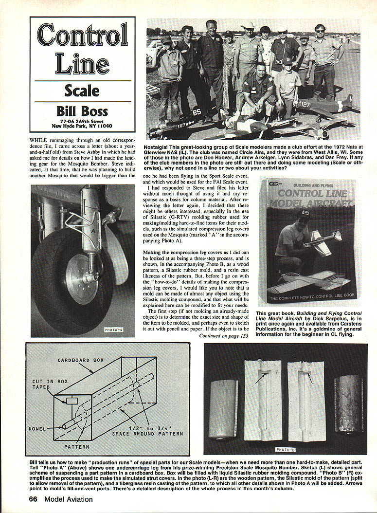
While rummaging through an old correspondence file, I came across a letter (about a year and a half old) from Steve Ashby asking for details on how I had made the landing gear for the Mosquito Bomber. Steve indicated he was planning to build another Mosquito larger than the one he had been flying in the Sport Scale event, and which would be used for the FAI Scale event.
I responded to Steve and filed his letter without much thought of using it as column material. After reviewing the letter again, I decided others might be interested—especially in the use of Silastic (G‑RTV) molding rubber for making hard-to-find items for models, such as the simulated compression leg covers used on the Mosquito (marked "A" in Photo A).
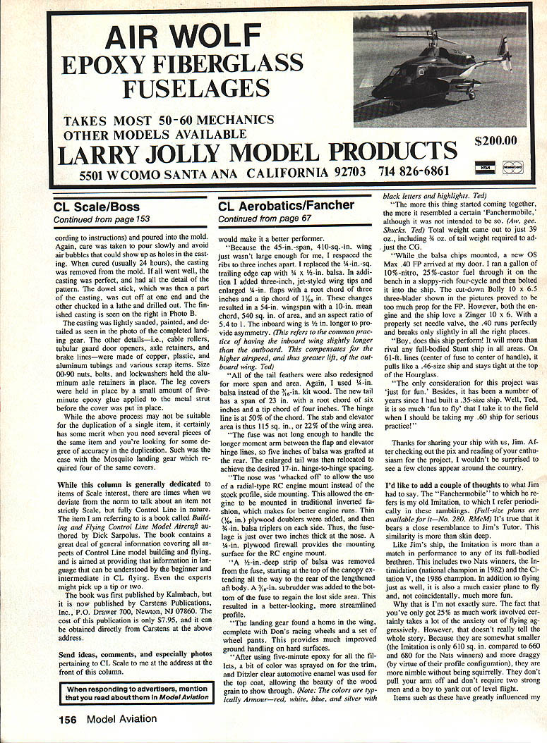
Making the compression leg covers can be viewed as a three-step process (illustrated in Photo B): a wood pattern, a Silastic rubber mold, and a resin cast likeness of the pattern. Note that a mold can be made of almost any object using Silastic molding compound; what follows can be modified to fit your needs.
Making the compression leg covers — overview
- Determine the exact size and shape of the item to be molded; sketch if helpful.
- Carve a wooden pattern to match that size and shape.
- Make a rubber mold from the pattern and cast the final parts in resin.
If the object is a landing gear strut cover (as in this example), make provision so that the cover can be placed over the working landing gear strut.
Pattern
- After determining the exact size and shape, I carved a wooden pattern from a block of hardwood. The block was predrilled for the size of the landing gear strut.
- The hole served two purposes: it accepted the working landing gear strut and was used for suspending the pattern during mold-making.
- The prototype compression leg covers were steel stampings joined with a series of rivets front and rear. The pattern and casting include this detail; I created it by gluing wood strips to the pattern and applying drops of epoxy glue to form the rivet heads.
Making the rubber mold
- The finished pattern was placed on a snugly fitting dowel stick, then fitted into a cardboard container allowing about 1/8 to 1/4 inch of clearance on all sides and ends of the pattern (see sketch).
- If the item’s shape does not lend itself to suspension, two or three straight pins pushed through the cardboard into the pattern will hold it in place.
- The Silastic G‑RTV molding compound used was made by Dow Corning Corporation. It is a two-part, two-color, room-temperature-curing silicone rubber. The rubber compound is white and the curing agent is red, which helps achieve a thorough, even mix. When properly mixed very slowly (to avoid air bubbles), the compound becomes light pink.
- After mixing, pour the compound slowly into the box, allowing it to form around the object and watching for air bubbles. Allow the mold to cure at least 24 hours.
- When cured, remove the cardboard box. Cut the mold in two so the pattern can be released. In the photo the mold was cut lengthwise down the side of the pattern with a single-edge razor blade. Care is needed to make an even cut so the mold will close tightly. Choose the mold separation point away from major mold areas.
- You now have two mold halves. Remove the dowel stick from the mold.
Preparing the mold for casting
- Cut small holes into the top of the mold to permit pouring of the fiberglass casting resin. One hole is for the pour and a second hole acts as an air vent.
Casting
- Place the dowel stick between the mold halves and hold them together with very light rubber bands (light bands prevent mold distortion).
- Mix polyester glass resin according to the instructions and pour into the mold. Pour slowly to avoid trapping air bubbles that show up as holes in the casting.
- When cured (usually about 24 hours), remove the casting from the mold. If all goes well, the casting will capture all the pattern detail.
- The dowel stick will be part of the casting; cut it off at one end, chuck the other end in a lathe, and drill it out. The finished casting is shown on the right in Photo B.
Finishing and assembly
- Lightly sand, paint, and detail the casting as seen in the photo of the completed landing gear.
- Other details—cable rollers, tubular guard door openers, axle retainers, and brake lines—were made from copper, plastic, aluminum tubing, and various scrap items.
- Size 00-90 nuts, bolts, and lockwashers held the aluminum axle retainers in place.
- The leg covers were attached with a small amount of five-minute epoxy applied to the metal strut before the cover was put in place.
- While this process may not be ideal for duplicating a single item, it has merit when you need several pieces with a good degree of accuracy. The Mosquito landing gear required four identical covers.
Note on molding versatility
A mold can be made of almost any object using Silastic G‑RTV, and the steps described above can be modified to suit different shapes and requirements.
Recommended book
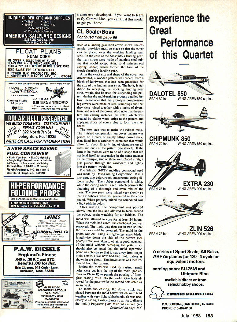
Although this column is generally dedicated to Scale interest, I’ll mention a useful Control Line book: Building and Flying Control Line Model Aircraft, by Dick Sarpolus. It contains a great deal of general information on CL model building and flying, written for beginners and intermediates; even experts might pick up a tip or two.
- Originally published by Kalmbach.
- Currently published by Carstens Publications, Inc., P.O. Drawer 700, Newton, NJ 07860.
- Price: $7.95 (available directly from Carstens at the above address).
Send ideas, comments, and especially photos pertaining to CL Scale to me at the address at the front of this column.
Transcribed from original scans by AI. Minor OCR errors may remain.

