
Control Line: Scale
Bill Boss 77-06 269th Street New Hyde Park, NY 11040
Introduction
Propellers used on our scale models fall into two basic categories: the ones we use for static display, and the propellers used for flying the model. In many instances we don't give too much thought to either one. You have probably seen contestants place a model on the flight line with a two‑bladed painted prop instead of the required three‑ or four‑bladed prop for the model. You may also have seen models struggle in the air when the engine size appeared right for the model, but the wrong prop was used.
This article covers both situations and presents the basics for making scale‑like propellers and selecting a flying prop for the model.
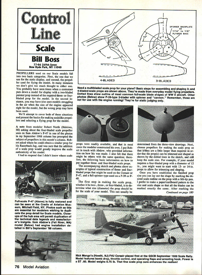
A note from modeler Robert North (Haleiwa, HI), asking about the four‑bladed scale propeller seen on Sam Abdow's P‑47 in one of the photos in my September 1988 column, prompted this subject. Robert asked where he could obtain a similar prop for his Razorback Jug, and was sure that the addition of a scale prop would greatly improve the model's authenticity. I had to respond that scale props are not readily available in most cases and are often constructed by the modeler. I put Robert in touch with Abdow, who provided information on how his was made. The following is basic information on how to put together three‑ and four‑bladed scale props.
Determining Size and Preparing Parts
The first step in making a scale prop (two‑, three‑, or four‑bladed) is to determine the diameter the prop should be for the scale of your model. This can usually be determined from three‑view drawings. Next, choose propellers for making the scale prop that are a little larger than required; this allows the prop(s) to be trimmed and shaped to the final outline while still keeping the scale size. For example, if your model requires a four‑bladed prop with a diameter of 12 in., you might start with 13‑ or 14‑in. props to allow for trimming and shaping.
Once you have established the finished prop size, lay out the shape by marking the desired scale outline on the prop with a felt‑tip pen. I prefer to make a paper or cardboard pattern to the size and scale shape so that all the blades can be marked exactly the same. After marking the blades, trim and shape to size.
Decide whether to shape the blades before joining them together or to join first and then shape; choose whichever is easiest or most comfortable. Recommended propeller types for making display props include:
- Rev‑Up
- Special Pro Series
- Top‑Rite
- Super M
Both types have basic shapes that lend themselves to easy modification and shaping; of course you can always carve a prop from scratch.
Constructing Four‑Bladed and Detailed Hubs
In the case of a four‑bladed prop, remember that half‑props and hubs often have cutaway areas and can be placed at right angles to each other while retaining the same thickness. A single‑blade four‑bladed prop used on the P‑47 model requires special attention to hub detailing and the prop case; good drawings and photos of the full‑scale prop will be needed.
Additional detail can be formed from balsa, hardwood scraps, or dowel stick material added to the hub and patiently shaped with hand tools or a Dremel‑type tool. Properly placed screw heads will produce a convincing scale look. Small screws for this purpose can be found at your local hobby shop, generally in the HO train department.
Three‑Bladed Props and Spinner‑Hidden Hubs
If the propeller is a three‑bladed type and the hub area is hidden by a spinner, all that is required is to produce a prop with the exposed blade area properly sized and shaped. Construction of the three‑bladed type can follow either method shown in the sketch:
- Cut the props (before or after shaping) at 30° angles and mount the individual sections on a wooden base or spinner backplate.
- If mounting on a backplate, small machine screws (for example, 2‑56) are adequate.
Mounting the sections by gluing on a thin wooden base permits mounting the prop on the airplane as you would a flying prop, without drilling and tapping the spinner backplate. If the three‑bladed prop is to be used on a model such as the Corsair and the hub area requires detailing, a circular wooden base cut to proper size will serve both as a base for the prop sections and for hub details.
Two photos accompanying the original article show the basic parts and completed display prop used by the author on a P‑39 Airacobra. The three‑blade sections were epoxied together and mounted on a ply base. The spinner used was the two‑piece screw‑together type made many years ago that required the prop to be mounted behind what we would normally think of as the spinner backplate. This type of spinner allowed easy mounting, with 2‑56 screws, of a simulated cannon barrel. The rear half of the spinner was then attached to the prop with small wood screws. A small hole cut into the end of the screw‑on spinner section allowed the cannon barrel to protrude as seen in the photo of the completed prop.
The last step in making your display prop is to paint the assembly in accordance with the color scheme chosen for the model and apply technical data and propeller insignia as required.
Selecting a Flying Propeller
When selecting a flying propeller, consider George Lieb's analogy: "What stops your car?" If you answered "the brakes," George says you're wrong — the brakes stop the wheels, which stop the tires, which stop the car. On ice the tires can't get a good grip and the car doesn't stop well, regardless of how good the brakes are.
We have a comparable situation with model airplanes. The engine doesn't pull the plane — the propeller does. The propeller must be matched to the engine and airplane. Along this line, a 14‑in. diameter, six‑inch pitch stunt prop would not carry a scale model through the pattern very well. Even though both props might be made for .60‑size engines, they must be matched to the intended use.
Even props labeled the same size but made by different manufacturers, or in different production runs, may perform differently. Unless you are very lucky, finding a suitable prop will require trial and error to match it to your engine and airplane.
This is especially true for the scale modeler, where prop blade area is often a major factor in propeller efficiency because of the model's higher drag. In the case of a fighter plane such as the P‑51 or P‑40, the model's frontal area is relatively small and the prop is the major moving aerodynamic surface, allowing for maximum use of the prop's blade area. In this case only a small portion of the prop on either end may be effective. Considerable experimentation may be required to find the right prop type, diameter, and pitch combination for the engine and use. You might even find after considerable experimentation that the engine used is too small.
A good starting point for prop selection is the manufacturer's recommendation for the engine size and type of model. Remember, a well‑matched engine, prop, and model combination will go a long way toward ensuring better model performance and limiting engine damage.
Closing
Please send ideas, comments, contest activity reports, and especially photos of CL scale activity to me at the address listed at the top of this column.
Transcribed from original scans by AI. Minor OCR errors may remain.

