
Control Line: Scale
Bill Boss 77-06 269th Street New Hyde Park, NY 11040
Throttle Control
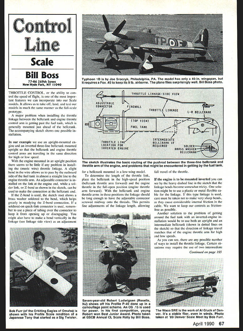
Throttle control — the ability to control speed in flight — is one of the most important features we can incorporate into our scale models. It allows us to take off, land, and taxi our models much the same as the full-scale prototype.
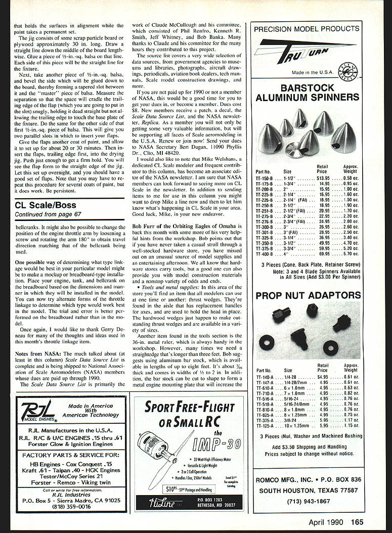
A major problem when installing the throttle linkage between the bellcrank and the engine throttle control arm is getting past the fuel tank, which is generally mounted just ahead of the bellcrank. The following notes describe one possible installation and several alternatives for different engine and airframe arrangements.
Throttle linkage installation (upright engine example)
- In the example shown, an upright-mounted engine is used with an inverted three-line bellcrank mounted upright so that the bellcrank and engine throttle control arms move in the same direction for high and low speed.
- With the engine upright, installing a music-wire throttle linkage is straightforward. A slight bend in the wire allows it to pass along the outboard side of the fuel tank in an almost straight line to the engine throttle arm.
- Use an adjustable connector on the link at the engine end to permit fine adjustments. At the bellcrank end you can use a soldered link or a Z-bend.
- If a Z-bend is used, solder a brass washer to the bend to steady the connection.
- If you use a soldered-on quick-link connector, place a piece of tubing over the connector to prevent it from opening or disengaging.
- You may need to add a vertical bend in the linkage (see linkage side-view) when routing between the three-line bellcrank and the engine throttle arm in a low-wing model.
Determining throttle-link length
- Place the bellcrank in the high-speed position (bellcrank throttle arm forward).
- Place the engine throttle in the full-open position (engine throttle arm forward).
- With the arms in these positions, the linkage should be long enough that the adjustable connector is screwed about midway onto its threads.
- This mid-position on the connector allows fine adjustment of the linkage length so the throttle can achieve full travel.
Inverted-engine solutions
- If the engine is mounted inverted, linkage bends can become trickier. One option is to use a plastic- or metal-flexible cable for the linkage. Avoid very sharp bends — they cause considerable internal friction. Keep controls as friction-free as possible.
- Another solution is to use an intermediate (or upright plus intermediate) bellcrank so the direction of linkage travel matches the engine throttle arm for high and low speeds. In some situations two intermediate bellcranks may be required.
- It may also be possible to change the position of the engine throttle arm by loosening its mounting screw and rotating the arm 180° so travel direction matches the bellcrank.
Breadboard mockup
- Before committing to an installation in the model, make a mockup or breadboard assembly.
- Place your engine, tank, and bellcrank on the breadboard according to the dimensions and mounting method you intend to use.
- Try alternate forms of throttle linkage on the breadboard to determine which works best. Trial and error is better done on the breadboard than inside the model.
Acknowledgements
- Thanks to Gerry Deneau for many of the thoughts and ideas used in this month's throttle linkage item.
Notes from NASA
- The Scale Data Source List is complete and is being shipped to National Association of Scale Aeromodelers (NASA) members whose dues are paid through 1990.
- The Scale Data Source List is primarily the work of Claude McCullough and his committee:
- Phil Renfro
- Kenneth R. Smith
- Jeff Whitney
- Bob Banka
- Many thanks to Claude and his committee for the many hours contributed to this project.
- The source list covers a wide range of resources: government agencies, museums and libraries, photographs, aircraft drawings, periodicals, aviation book dealers, technical manuals, scale model construction drawings, and more.
- If you are not paid up for 1990 or not a NASA member, now is a good time to renew or join. Dues are $8. New members receive a patch, a decal, the Scale Data Source List, and the NASA newsletter Replica.
- Send dues to: NASA Secretary Bert Dugan, 11090 Phyllis St., Clio, MI 48420.
- Note: Mike Welshans, a dedicated CL scale modeler and frequent contributor to this column, has become an associate editor of the NASA newsletter. NASA members can look forward to more CL Scale coverage. Consider sending items to Mike as well as to this column.
Workshop Hints (Bob Furr)
Bob Furr of the Orbiting Eagles of Omaha offers these helpful hardware-store finds and tips:
- Hardware stores can be an excellent source of model supplies and odd items for the workshop.
- Thrust wedges: found near replacement axe handles; hardwood wedges make outstanding thrust wedges and come in a variety of sizes.
- Measuring and straightedge materials:
- A 36-inch metal ruler is handy, but for longer straightedges consider aluminum bar stock.
- Aluminum bar stock is available in lengths up to eight feet, about 1/2 inch thick, and widths from 1/8 to 2 inches.
- The bar stock can be cut to shape to form a metal engine mounting plate that will increase the strength and stability of the mounting.
Good luck with your throttle-linkage installations and workshop projects.
Transcribed from original scans by AI. Minor OCR errors may remain.

