
Control Line: Scale
Bill Boss 77-06 269th Street New Hyde Park, NY 11040
Rivet simulation (flush-type rivets)
RIVET SIMULATION has been a topic in this column several times. We've simulated rivets using drops of epoxy or other glues, sharpened tubing, and a dressmaker's marking wheel.
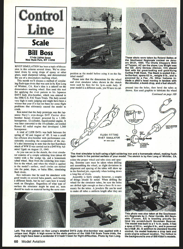
This month describes a method for simulating flush-type rivets sent by Ken Long of Whittier, CA. Ken used this tool to apply the rivet pattern to his Japanese D4Y3 Judy dive-bomber entered in the 1986 U.S. FAI Team Trials. The Judy scored very high in static judging and might have won that year if not for flight problems that caused the model to crash.
Ken noted that the Judy prototype was the Japanese Navy's D4Y carrier dive-bomber Suisei (Comet), originally powered by a 1,200-hp, 12-cylinder, liquid-cooled engine. It was later converted to the 14-cylinder, air-cooled Kensei 62 radial engine developing 1,560 hp. A total of 2,038 D4Ys was built between spring 1942 and August 1945. It was a small but efficient dive-bomber with performance exceeding contemporary competition. The last Kamikaze attack of WWII was carried out in a D4Y4 by Admiral Ugaki on August 15, 1945.
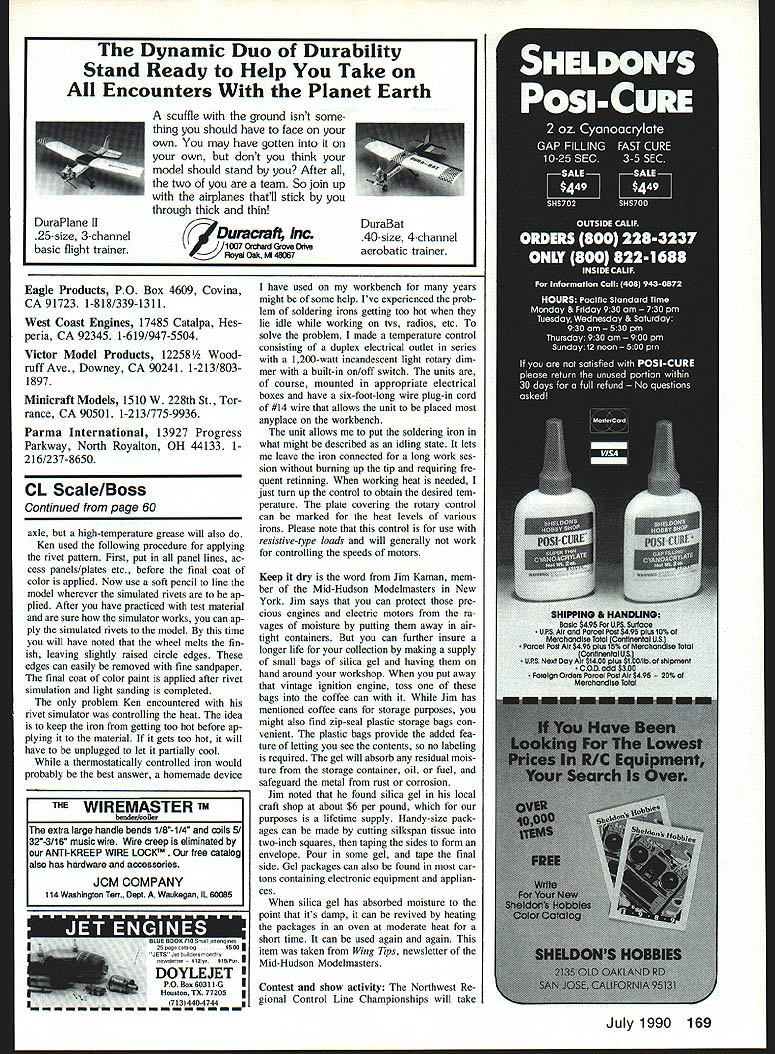
As shown in Ken's sketch, the rivet simulator consists of a simple soldering iron (about 40 watts) with a flat wedge tip and a homemade tubed wheel. Heat from the soldering iron transfers to the wheel; when the wheel is applied to the model surface, small circles are melted into the paint, dope, or balsa filler, simulating flush rivets.
Ken used the simulator with good results on several balsa panels with different finishes, but he is unsure how it will perform on fiberglass. Regardless of surface type, test on scrap material of the same composition as the model before working on the finished model.
Please note the wheel and tube dimensions shown in the sketch were used by Ken for his 1/2-in.-scale Judy. If your model is a different scale, calculate proper wheel/tube sizes and spacing. Extreme care is required when drilling and assembling the wheel; slight deviations in alignment and spacing will show up, especially when looking down a long line of rivets.
Wheel construction and assembly
Assembly is fairly simple, with a few important notes:
- Drill holes for the simulator tubes so they are a force fit; the tubes should require pressing into the holes.
- After pressing tubes into the holes, use a jeweler's file to make all tubes a uniform length.
- Bevel the tube ends as shown in the sketch.
- Ken used graphite to lubricate the wheel and the axle; a high-temperature grease will also do.
Extra care: slight deviations in alignment or spacing will be visible on the finished job. Test the assembled wheel on scrap before use.
Procedure for applying the rivet pattern
Ken's recommended procedure:
- Put in all panel lines, access panels/plates, etc., before the final coat of color is applied.
- Use a soft pencil to mark where simulated rivets are to be applied.
- Practice on test material until you are sure how the simulator behaves.
- Apply simulated rivets to the model. The wheel melts the finish slightly, leaving slightly raised circles or dimples.
- Remove the raised edges with fine sandpaper.
- Apply the final coat of color paint after rivet simulation and light sanding are completed.
The main problem Ken encountered was controlling heat. Keep the iron from getting too hot before applying it; if it overheats, unplug it to let it cool.
Temperature control for the soldering iron
While a thermostatically controlled iron is ideal, the author describes a homemade control used for many years:
- A duplex electrical outlet wired in series with a 1,200-watt incandescent-light rotary dimmer that has a built-in on/off switch.
- Units mounted in appropriate electrical boxes with a six-foot cord of #14 wire for placement on the workbench.
- The control allows the iron to be left in an "idling" state without burning the tip. Turn up the control for working heat.
- Mark the plate covering the rotary control for heat levels of various irons.
Note: This control is for resistive-type loads and will generally not work for controlling motor speeds.
Protecting engines and motors from moisture
Jim Kaman, member of the Mid-Hudson Modelmasters (NY), recommends storing engines and electric motors in airtight containers with small bags of silica gel to protect against moisture.
- Store engines in coffee cans, zip-seal plastic bags, or other airtight containers.
- Make silica-gel packets using silkspan tissue cut into squares, taped into envelopes; place one sealed packet in the engine box.
- Silica gel absorbs residual moisture from the container, oil, or fuel and prevents rust/corrosion.
- Silica gel can be purchased at craft shops (Jim found it at about $6 per pound).
- To revive damp silica gel, heat the package in an oven at a low temperature for a short time; it can be reused.
(This item was taken from Wing Tips, newsletter of the Mid-Hudson Modelmasters.)
Contest and show activity
- Northwest Regional Control Line Championships
- Date: May 26–27, 1990
- Location: Mahlon Sweet Airport, Eugene, OR
- Features: Nearly every CL event in the rule book; three asphalt circles, four grass circles, covered benches, on-field hobby shop, rest rooms, concessions, and camping space. Precision and Sport Scale events will be flown.
- Contact: CD Morris Gilbert, 170 Formac, Eugene, OR 97404; tel. 1-503/688-4357
- Cradle of Aviation Museum annual model and full-scale aviation display
- Date: June 2–3, 1990
- Location: Mitchell Field, NY
- Notes: This year's event is in memory of Leo Spencer. Modelers are encouraged to display Scale models to show the public what model aviation is about.
- Contact: Tony Rusticano, 38 Riverside Dr., Rockville Centre, NY 11570; tel. 1-516/764-2978
Please send comments, contest activity reports, and especially photos of CL Scale activity to the address at the top of this column.
Transcribed from original scans by AI. Minor OCR errors may remain.

