

Control Line: Scale
Author
Bill Boss 77-06 269th Street New Hyde Park, NY 11040
Electronic Controls
During the past few years I have presented various information on the subject of electric and/or electronic controls for CL Scale. In February and March 1984 I presented material on the use of electric servos. The October 1984 column described Clancy Arnold's UTronic System. In the January 1988 issue I again discussed electronic controls as well as electric servo control of flaps.
The most recent letters to come my way on electronic controls were from two CL Scale builders in California—Grant Heistand of Reseda and Fred Cronenwett of Canoga Park. Both men described electronic control systems they are experimenting with. Their systems are made from converted radios and equipment obtained from Ace R/C.
Supplementing comments from Grant and Fred with some work of my own, I will cover in this column and the next the construction of an electronic system using an encoder and decoder, plus various parts obtainable from Ace R/C and your local electronics supply shop. This month's focus is on the encoder.
Before explaining our project in detail, let's review the basic principles of Control Line system operation as presented in my October 1984 column.
In RC operation the movement of a transmitter control stick varies a DC voltage input to the encoder for a particular system channel. The encoder generates a series of pulses that are directly proportional to the movement of the control. The pulses are passed to the RF section where they modulate the signal being broadcast.
When the signal is picked up by the receiver, the process is reversed. The signal passes through the RF section to the decoder, which interprets the pulse stream and activates the servo operation for a designated channel.
Our CL system simply eliminates the RF section at both ends, replacing it with a pair of insulated lines between the handle and the plane. Instead of an RF signal being generated or transmitted, a series of encoded electrical pulses is sent up the lines to the model.
The system employs a generic 7-channel encoder, but this unit uses only two of the channels. One channel uses an AUX/TRIM pot control that provides proportional control for flaps, engine, or any operation that requires incremental control. The second channel is switch operated and might be used for bomb-bay door operation, gear retraction, or any other on-off operation.
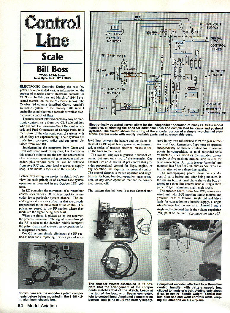
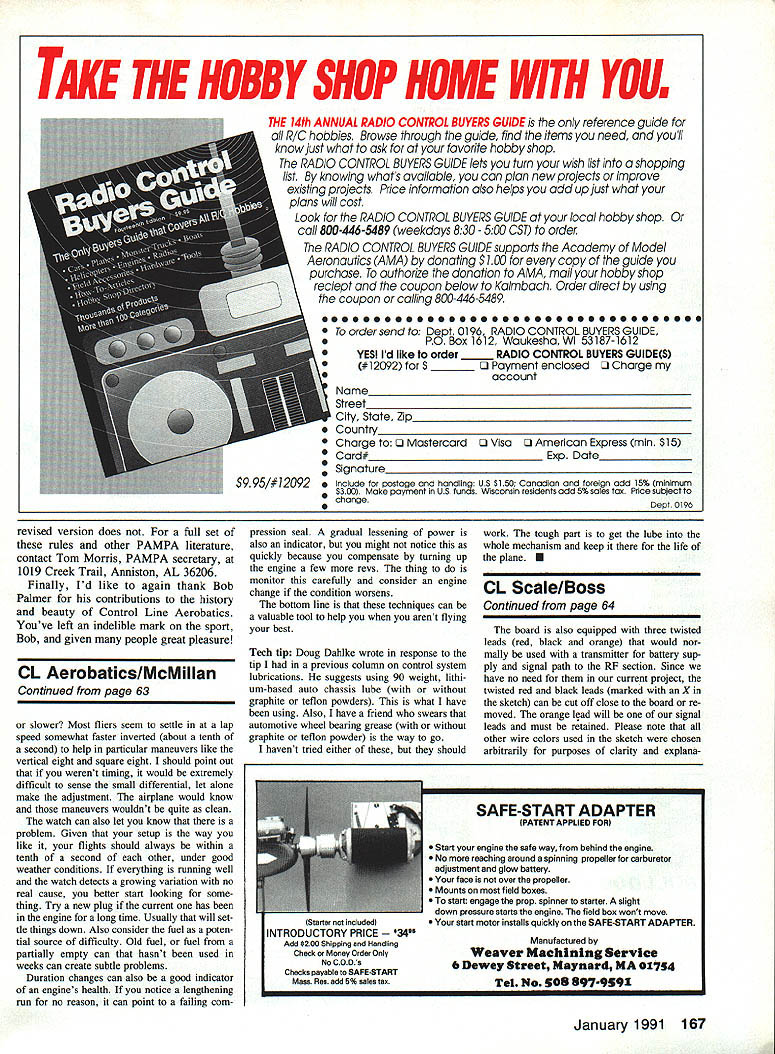
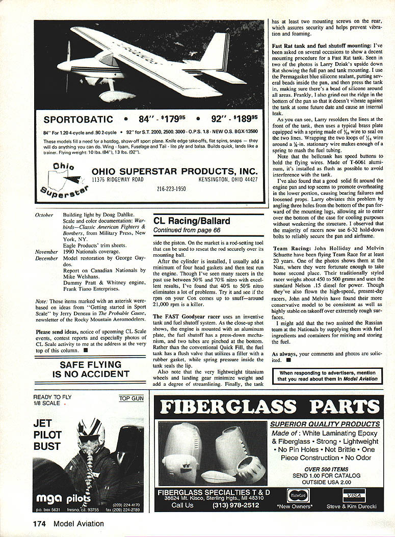
The system detailed here is a two-channel unit used in my own refurbished P-39 for gear retraction and flaps. Remember, flaps must be operated independently of throttle control for maximum points in competition. A mini expanded-scale voltmeter (ESV) monitors the encoder battery supply. A five-position terminal strip is used for wire connections. All parts (except batteries) are mounted in a 3-5/8 × 3 × 2 in. chassis box, which in turn is attached to a three-line handle.
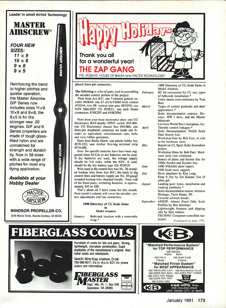
Photos accompanying the original article show the encoder control parts before and after being mounted in the chassis box. A third photo shows the box attached to a three-line control handle using a short piece of 3/8 in. aluminum right-angle stock.
Encoder board and wiring
The encoder board from Ace R/C comes as a wired unit with 2-56 machine-screw mounts and prewired leads as follows:
- Single red and black leads for connection to a battery supply.
- Single white/orange lead connected to channel 1.
- Single red/white lead that is the voltage-regulation (VR) point of the unit.
- Three twisted leads (red, black and orange) that would normally be used with a transmitter for battery supply and signal path to the RF section. In this project the twisted red and black leads are not needed and can be cut off close to the board or removed. The orange lead will be used as one of the signal leads and must be retained.
Note: All other wire colors used in sketches or explanations were chosen arbitrarily for clarity. Wire color can be anything you choose.
In addition to prewiring channel 1, Ace R/C has wired channels 2 and 3 with 2.8k (2,800 ohm) resistors, shown as RX in the sketch. Channels 4 to 7 are strapped to terminal B (dotted line on the underside of the board). Ace explained that the encoder design requires channels 1 to 3 to appear active at all times—thus the 2.8k biasing resistors—and channels 4 to 7 must be strapped to ground unless used. If these rules are not followed the encoder will not function properly.
If channel 2 or 3 is used, the 2.8k resistor must be removed and replaced with an appropriate control device. If any channel between 4 and 7 is used, the strap on the back of the board for that channel must be removed.
The wiring for two typical control devices is as follows:
- Gear retraction control: a single-pole double-throw (SPDT) ON-ON switch with 5k trim pots soldered to the outside terminals. The center terminal of the switch is connected to channel 1 (replacing the original white/orange lead). The center terminal of each trim pot is connected to the VR and B terminals of the terminal strip via red and black leads.
- Flap control: an Ace R/C 5k AUX/TRIM pot connected to channel 2 (after removing the 2.8k resistor) in the same manner as the gear control. Channel 3 remains biased with the 2.8k resistor unless used.
The Mini-ESV, also an Ace R/C product, is available for Ni-Cd or dry battery use. It comes equipped with red and black leads and includes mounting instructions. Connect its leads to the B+ and B- terminals of the terminal strip. The ESV has a green-and-red scale that shows battery condition; a reading in the green zone is okay, while the red zone indicates the batteries must be recharged or replaced.
Complete the wiring by connecting the VR (red/white), signal (orange), and B+ (red) and B- (black) leads of the encoder board to their respective terminals on the terminal strip. Provide a pair of signal leads from the Sig and B terminals; these leads will be connected to the control lines with Deans connectors. Finally, provide leads from the B+ and B- terminals to the battery supply.
Two 4.8-volt 500 mAh AA Ni-Cd battery packs wired in series provide the 9.6 volts required by the encoder. The batteries are mounted in a plastic box, complete with on-off switch and homemade belt clip. Power lead connection to the battery box is via an Amphenol connector.
The completed encoder is attached to the three-line control handle; the battery supply box is clipped to the modeler's belt. Adding about 5 oz to the control-handle weight lets the pilot see and work the controls while keeping full attention on the airplane.
Parts list
Parts from Ace R/C:
- One 7-channel generic encoder #404EA
- One S7 AUX/TRIM lever control #15G44
- Two 5K vertical trim pots #RV078
- One 9.6V Mini-ESV (Ni-Cd) #22K11
- One each Deans connectors #19K20F and #19K20M
Parts from your local electronics store:
- One CG Electronics BAT-handle SPDT switch #35-004
- One CG Electronics chassis box #10-066
- One three-pin Amphenol connector set (male and female) or equivalent
- Miscellaneous nuts, bolts and rubber grommets
Parts from Radio Shack:
- One plastic hobby box #270-222
- One Archer five-lug terminal strip #274-688
Other notes:
- No specific batteries are required; Ni-Cd or dry batteries can be used. If dry batteries are used, the voltage supply should be 9.0 volts and the ESV (if used) should be the dry-battery type (D) #22K10.
- Wire used in the control box was No. 26 stranded hookup wire from Ace R/C; leads to the control lines and battery supply are No. 20 gauge stranded hookup wire obtained locally.
- Total cost of the listed parts, excluding batteries, is approximately $45–$50.
Closing
That's about all I have room for this month. Next month's column will cover the decoder, system adjustments and line connectors.
For other PAMPA literature contact Tom Morris, PAMPA secretary, 1019 Creek Trail, Anniston, AL 36206.
Transcribed from original scans by AI. Minor OCR errors may remain.

