
Control Line: Scale
Bill Boss 77-06 269th Street New Hyde Park, NY 11040
Electronic control system — Part III
This month concludes a three‑part series on setting up and operating a two‑channel electronic control system. Earlier columns explained the encoder and decoder and included information on system operation. This installment covers overall wiring, batteries, insulated control lines and a method for insulating connectors.
System wiring and connectors
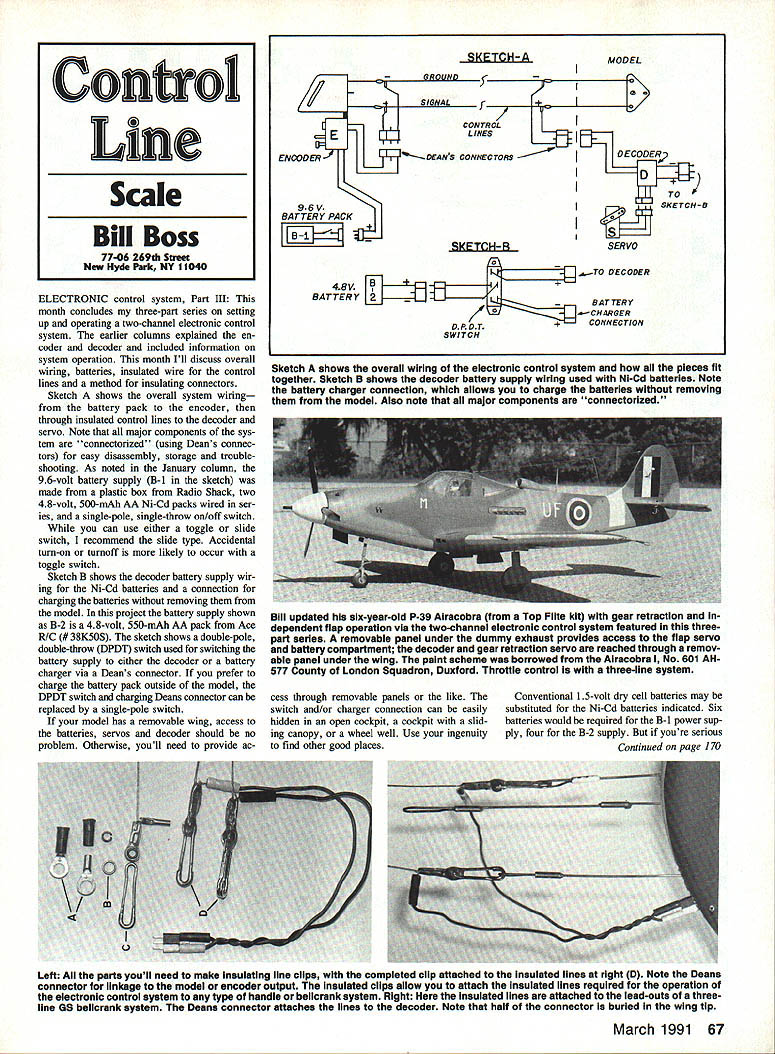
- Sketch A shows the overall system wiring: battery pack (B‑1), encoder, insulated control lines, decoder and servo.
- All major components are connectorized using Deans connectors for easy disassembly, storage and troubleshooting.
- The B‑1 supply used in the sketches is a 9.6‑volt pack made from two 4.8‑volt, 500‑mAh AA Ni‑Cd packs wired in series and housed in a Radio Shack plastic box. A single‑pole single‑throw on/off switch is used; a slide switch is recommended over a toggle to reduce accidental turn‑on/off.
Battery supplies and charging (Sketch B)
- Sketch B shows decoder battery wiring for Ni‑Cd batteries and a charging connection that allows charging without removing the pack from the model.
- The example B‑2 pack is a 4.8‑volt, 550‑mAh AA Ni‑Cd (Ace R/C #381505). A double‑pole double‑throw (DPDT) switch is shown for switching the pack between the decoder and a charger via a Deans connector.
- If you prefer to charge the pack outside the model (or have removable wing access), the DPDT switch and charging Deans connector can be replaced with a single‑pole switch. Otherwise provide a charging connector on the model.
- Both Ni‑Cd packs should provide about two hours of system operation when fully charged. Conventional 1.5‑volt dry cells may be used instead (six cells for B‑1, four for B‑2), but Ni‑Cds and a charger are recommended for serious use.
Installation access and example
- If your model has a removable wing, access to batteries, servos and decoder is straightforward. Otherwise, provide access via removable panels. Switches and charger connections can be hidden in an open cockpit, under a sliding canopy, or in a wheel well—use ingenuity to find convenient locations.
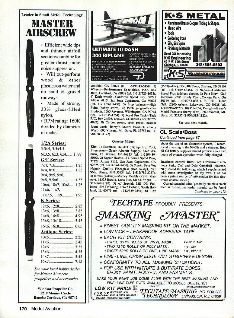
- Example: a six‑year‑old Top Flite P‑39 Airacobra was updated using this two‑channel system. Gear retraction and dependent flap operation are implemented electronically. Access is via a removable panel under the dummy exhaust for flap servo, battery compartment and decoder; the gear‑retraction servo is reached through a removable wing panel.
Insulated control lines
- Ted Croonenwelt (Canoga Park, CA) and Dale Campbell (Newton, NH) provided the following tips (supplemented by the author).
- Coated stranded fishing‑leader wire (generally stainless steel, available in 50‑ to 200‑lb test) works well as an insulated control line. This is the same material used for leader and tracer wires in bellcrank (three‑line) systems.
- The coating is not designed to completely cover each individual strand, so it can split when bent sharply and expose metal. Use heat‑shrink tubing at the ends for extra insulation and to anchor trolley crimps; plastic shrink tubing can also be used along the line length. Surf‑shop coated leader is preferred.
- Control lines insulated this way can be used with any handle or bellcrank system. If you prefer the standard three‑line bellcrank throttle system, make the third line from the same material to ensure uniform strength, drag and wear.
Insulating line connectors
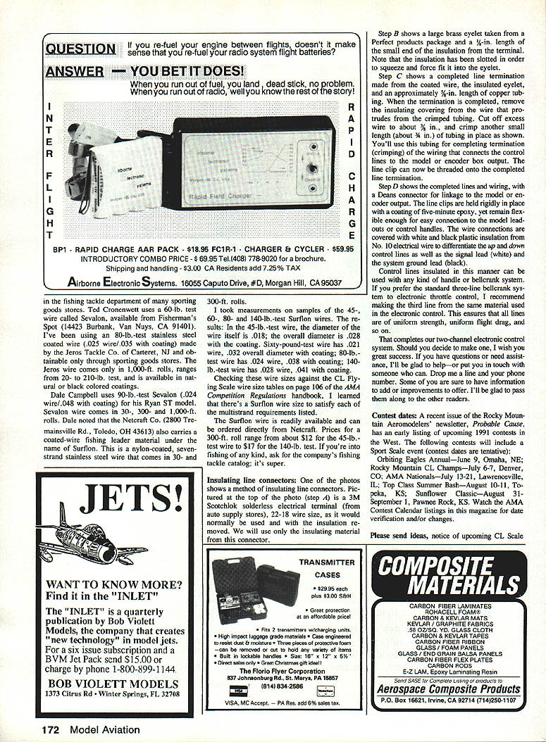
- Step A: Use the insulating portion of a 3M Scotchlok solderless electrical terminal (22‑18 wire size) from an auto supply store. Remove and discard the metal terminal; keep only the small insulating sleeve.
- Step B: Obtain a large brass eyelet (from Perfect Products or similar) and a 1/4‑in. length of the terminal insulation. Slot the insulation so it can be squeezed and forced into the eyelet.
- Step C: Form a line termination using the coated wire, the insulated eyelet, and an approximately 3/8‑in. length of copper tubing. After crimping, remove the insulating covering from the wire protruding from the crimped tubing, trim the exposed wire to about 3/16 in., then crimp a second small length (about 3/16 in.) of tubing over it. This small tubing is used for completing the termination when connecting control lines to the model or encoder box output. Thread the line clips onto the completed termination.
- Step D: The completed lines and wiring include a Deans connector for linkage to the model or encoder output. Line clips are held rigidly in place with a coating of five‑minute epoxy yet remain flexible enough for easy connection to lead‑outs or control handles. Cover the wire connections with white and black plastic insulation (from No. 10 electrical wire) to differentiate the signal lead (white) and the system ground lead (black).
Final notes
That completes the two‑channel electronic control system. If you decide to build one, best of success. If you have questions or need assistance, send a note and your phone number; I'll be glad to help. Contributions, improvements and additional information from readers are welcome and will be passed along.
Contest dates
A recent Rocky Mountain Aeromodelers newsletter listed tentative 1991 contests that include a Sport Scale event:
- Orbiting Eagles Annual — June 9, Omaha, NE
- Rocky Mountain CL Champs — July 6–7, Denver, CO
- AMA Nationals — July 13–21, Lawrenceville, IL
- Top Class Summer Bash — August 10–11, Topeka, KS
- Sunflower Classic — August 31–September 1, Pawnee Rock, KS
Watch the AMA Contest Calendar listings in this magazine for date verification and changes. Please send ideas, notices of upcoming CL Scale events, or other suggestions to me; I'll be glad to pass them along to readers.
Transcribed from original scans by AI. Minor OCR errors may remain.

