
Control Line: Scale
Bill Boss 77-06 269th Street New Hyde Park, NY 11040
OVERSEAS MAIL is something I always welcome since the writers usually have some interesting things to say about modeling and flying activities in other parts of the world.
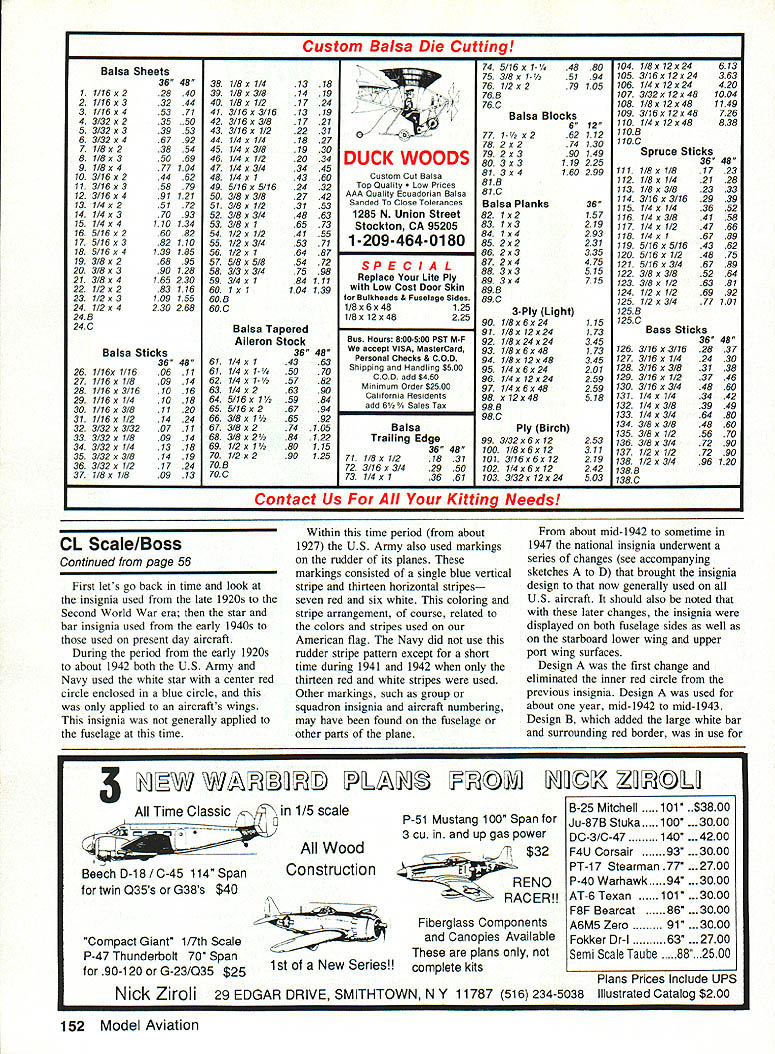
Such is the case in a letter received from Karl-Georg Krafft of Germany, who is a regular reader of Model Aviation. Karl-Georg said that for many years CL Scale in Germany (as well as in many other European countries) was dead. However, in the past five years there have been a number of local contests; and in 1991, even a national competition. This kind of news is great for the CL Scale fraternity because the more activity there is in foreign countries, the better the chance there is for greater participation in CL Scale World Championships. Karl-Georg also sent along some photos of models he's built and used in recent competitions.
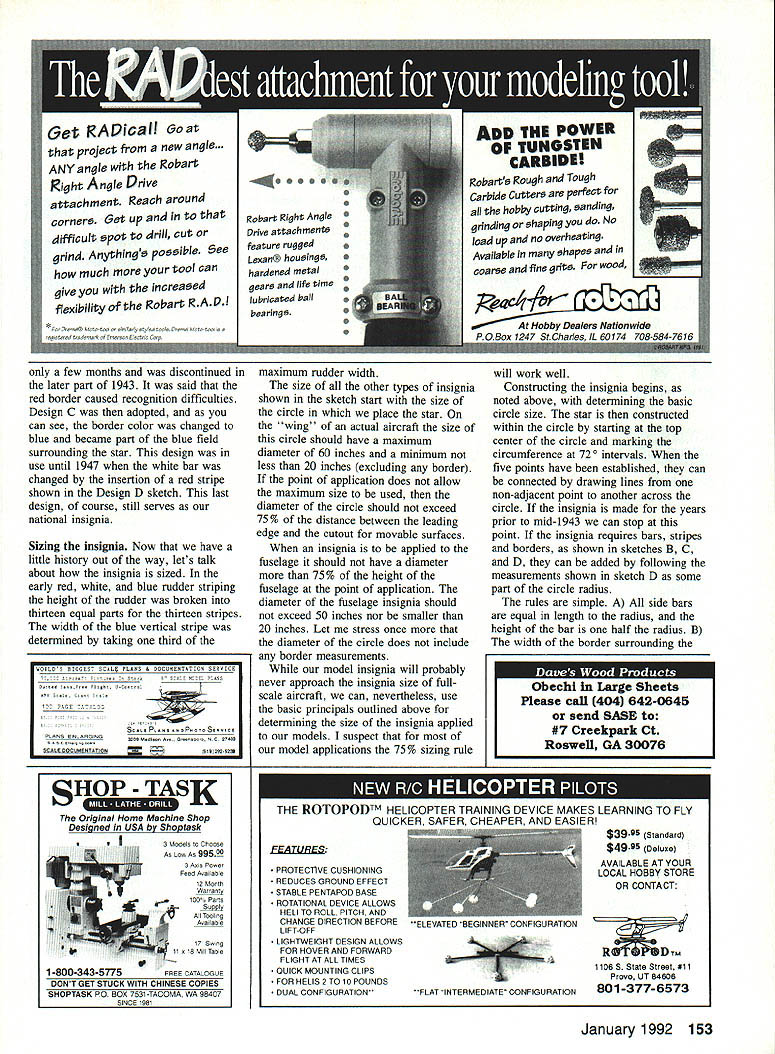
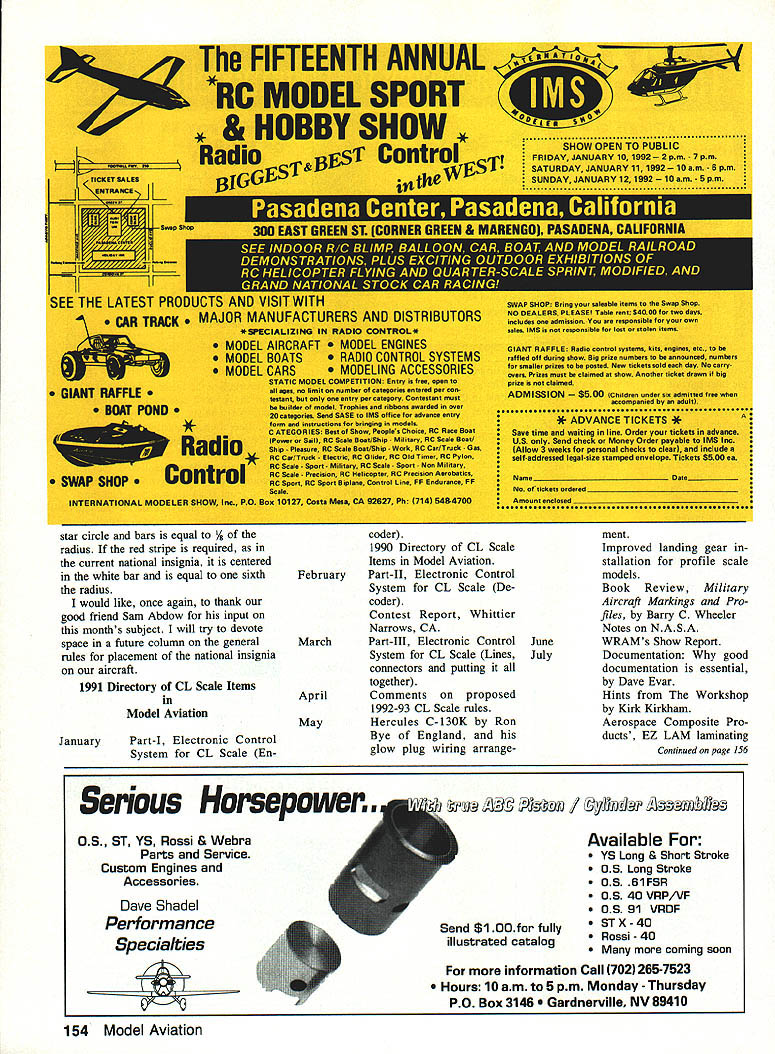
The accompanying photos show his Curtiss Gulfhawk, Curtiss Goshawk, Gee Bee Y and Wedell Williams "We Will Jr." racer. The Curtiss Gulfhawk and Gee Bee have won in several competitions. All are great-looking models and show excellent workmanship. I hope to be hearing more about scale modeling in Germany and other countries from Karl-Georg in the future.
Aircraft lettering and how to calculate the size, spacing and placement on an aircraft was the main subject of the September 1991 column. That column also had some words on the placement of squadron code grouping. This month we'll talk about the U.S. "Stars and Bars" insignia and how to determine the size of the star, bars, stripes, and border.
U.S. insignia: history overview
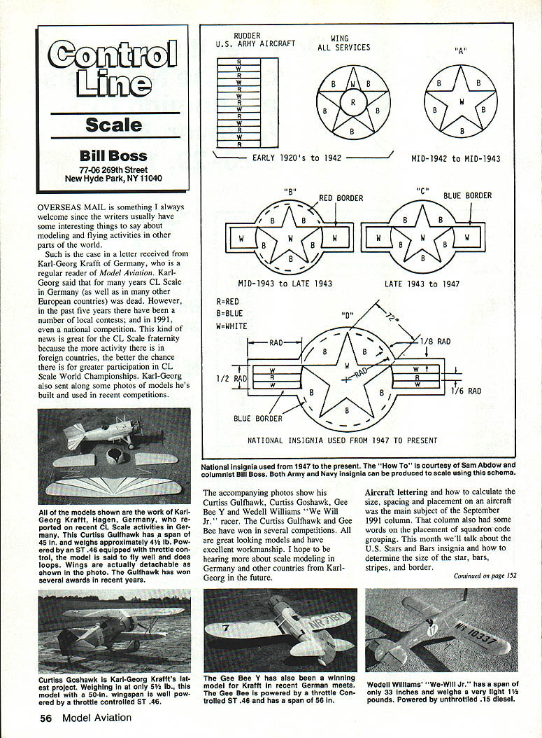
First, let's go back in time and look at the insignia used from the late 1920s to the Second World War era, then the star-and-bar insignia used from the early 1940s to those used on present-day aircraft.
During the period from the early 1920s to about 1942 both the U.S. Army and Navy used the white star with a center red circle enclosed in a blue circle; this was only applied to an aircraft's wings. This insignia was not generally applied to the fuselage at that time.
Within this time period (from about 1927) the U.S. Army also used markings on the rudder of its planes. These markings consisted of a single blue vertical stripe and thirteen horizontal stripes—seven red and six white. This coloring and stripe arrangement, of course, related to the colors and stripes used on the American flag. The Navy did not use this rudder-stripe pattern except for a short time during 1941 and 1942 when only the thirteen red and white stripes were used.
Other markings, such as group or squadron insignia and aircraft numbering, may have been found on the fuselage or other parts of the plane.
From about mid-1942 to sometime in 1947 the national insignia underwent a series of changes (see accompanying sketches A to D) that brought the design to what is now generally used on all U.S. aircraft. It should also be noted that with these later changes the insignia were displayed on both fuselage sides as well as on the starboard lower wing and the upper port wing surfaces.
Design A was the first change and eliminated the inner red circle from the previous insignia. Design A was used for about one year, mid-1942 to mid-1943.
Design B, which added the large white bar and surrounding red border, was in use for only a few months and was discontinued in the later part of 1943. It was said that the red border caused recognition difficulties. Design C was then adopted; the border color was changed to blue and became part of the blue field surrounding the star. This design was in use until 1947 when the white bar was changed by the insertion of a red stripe shown in the Design D sketch. This last design, of course, still serves as our national insignia.
Sizing the insignia
In the early red, white, and blue rudder striping the height of the rudder was divided into thirteen equal parts for the thirteen stripes. The width of the blue vertical stripe was determined by taking one third of the maximum rudder width.
The size of all the other types of insignia shown in the sketches starts with the size of the circle in which the star is placed. On the wing of an actual aircraft the diameter of this circle should have a maximum of 60 inches and a minimum not less than 20 inches (excluding any border). If the point of application does not allow the maximum size to be used, then the diameter of the circle should not exceed 75% of the distance between the leading edge and the cutout for movable surfaces.
When an insignia is to be applied to the fuselage it should not have a diameter more than 75% of the height of the fuselage at the point of application. The diameter of the fuselage insignia should not exceed 50 inches nor be smaller than 20 inches. Let me stress once more that the diameter of the circle does not include any border measurements.
While our model insignia will probably never approach full-scale insignia size, we can nevertheless use the basic principles outlined above for determining the size of the insignia applied to our models. For most model applications the 75% sizing rule will work well.
Constructing the insignia
Constructing the insignia begins with determining the basic circle size. The star is then constructed within the circle by starting at the top center of the circle and marking the circumference at 72° intervals. When the five points have been established, they can be connected by drawing lines from one non-adjacent point to another across the circle. If the insignia is made for the years prior to mid-1943 we can stop at this point.
If the insignia requires bars, stripes and borders (as in designs B, C, and D), they can be added by following the measurements shown in sketch D as some part of the circle radius. The rules are simple:
- Side bars: length = radius of the circle; height = 1/2 of the radius.
- Border width (the band surrounding the circle): = 1/12 of the radius.
- Spacing between the star circle and the side bars: = 1/8 of the radius.
- Red stripe (when required, as in the current national insignia): centered in the white bar and equal to 1/6 of the radius.
I would like, once again, to thank our good friend Sam Abdow for his input on this month's subject. I will try to devote space in a future column to the general rules for placement of the national insignia on our aircraft.
1991 Directory of CL Scale Items
Model Aviation
January
- Part I: Electronic Control System for CL Scale (Encoder).
February
- 1990 Directory of CL Scale Items in Model Aviation. Part II: Electronic Control System for CL Scale (Decoder).
March
- Contest report: Whittier Narrows, CA.
April
- Part III: Electronic Control System for CL Scale (Lines, connectors and putting it all together).
May
- Comments on proposed 1992–93 CL Scale rules.
June
- Hercules C-130K by Ron Bye of England, and his glow plug wiring arrangement.
July
- Improved landing gear installation for profile scale models.
- Book Review: Military Aircraft Markings and Profiles, by Barry C. Wheeler.
- Notes on N.A.S.A. WRAM'S show report.
- Documentation: Why good documentation is essential, by Dave Evar.
- Hints from the Workshop by Kirk Kirkham.
- Aerospace Composite Products' EZ-LAM laminating cement, Kev-Cord for control cables and NO-FRAY carbon fiber tape.
August
- Dummy Engine by Sam Abdow. You don't need a machine shop to make this one.
- Book Review: Fighters of the U.S. Air Force, by Robert F. Dorr and David Donald.
- Workshop Hints by Kirk Kirkham.
September
- Lettering on military planes: formulas for sizing and spacing.
- Coverite: new 21st Century space-age paint, film and fabric.
October
- On-board glow starter by Dave Willis.
- Micro Mark: small modelers' tools.
- Caution on submitting photos for publication.
- Contest report: Broken Arrow Stunt Contest, Valley Park, MO.
November
- 1991 Nationals coverage.
December
- Contest report: Queen City U-Control Club, Cincinnati, OH.
- Unique plaque awards.
- Techtape masking technology: new masking tape types.
- Video on electronic controls by Dale Campbell.
Please send ideas, notice of upcoming CL Scale events, contest reports and, especially, photos of CL Scale activity to me at the address at the very top of this column.
Transcribed from original scans by AI. Minor OCR errors may remain.

