
Control Line: Scale
Bill Boss 77-06 269th St., New Hyde Park, NY 11040
Improve the appearance of your profile scale model
George Gaydos of the Garden State Circle Burners, a long-time promoter of the Profile Scale event, is also an innovator when it comes to improving the appearance of a Profile Scale model.
Gaydos says the two worst-looking features of a profile model are the way the engine is mounted and the way the pushrods are generally run or mounted on the outside of the fuselage. The Profile Scale rules allow the use of a one-inch-thick fuselage (and/or engine nacelles on a multiengine model). Gaydos suggests using this thickness to improve the model's appearance.
His first suggestion is to center the engine in the fuselage or nacelle; second, take advantage of the one-inch thickness to hide the pushrods. This construction method was used by Gaydos on his profile B-26.
Centering the engine
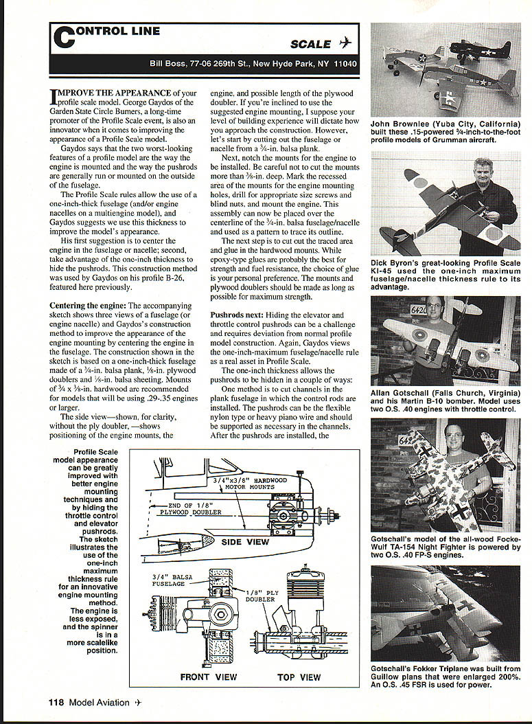
The construction shown below is based on a one-inch-thick fuselage made from a 3/4-in. balsa plank, 1/8-in. plywood doublers and 1/8-in. balsa sheeting. For models using .29–.35 engines or larger, mounts of 3/4 x 3/8-in. hardwood are recommended.
Suggested construction steps:
- Cut out the fuselage or nacelle from a 3/4-in. balsa plank.
- Notch the mounts for the engine to be installed. Do not cut the mounts more than 3/8-in. deep.
- Mark the recessed area of the mounts for the engine mounting holes, drill for appropriately sized screws and blind nuts, and mount the engine.
- Place this assembly over the centerline of the 3/4-in. balsa fuselage/nacelle and use it as a pattern to trace its outline.
- Cut out the traced area and glue in the hardwood mounts. Epoxy-type glues are recommended for strength and fuel resistance, but glue choice is personal preference.
- Make the mounts and plywood doublers as long as possible for maximum strength.
The side view (omitted here) shows positioning of the engine mounts, the engine, and the possible length of the plywood doubler. Your level of building experience will dictate construction details, but the above steps provide a practical outline.
Pushrods
Hiding the elevator and throttle control pushrods requires deviation from normal profile model construction. The one-inch fuselage thickness allows the pushrods to be hidden in a couple of ways:
- Cut channels in the plank fuselage for the control rods. Use flexible nylon pushrods or heavy piano wire and support them as necessary in the channels. After installation, cover the channels with 1/8-in. balsa sheeting and finish the fuselage as usual.
- Combine plank construction in the engine area with built-up/former-type construction in the rear of the fuselage. This hides pushrods, improves appearance, and usually results in a lighter model.
- Alternatively, construct a completely built-up fuselage while staying within the one-inch maximum thickness rule.
Model improvements
Using this construction method improves model appearance in several ways:
- Hides much of the engine; normally ugly mounting bolts and nuts are concealed.
- Centers the engine so spinners align with fuselage/nacelle outlines in top and front views.
- In multiengine models, centers engines in their basic scale positions and allows better propeller clearance, especially for engines mounted in the inboard wing panel closest to the fuselage.
A closing thought: the idea is simple and practical and can greatly improve the appearance of your profile scale models.
Control Line: Scale
Fuel tank ideas
How about someone showing how to improve the appearance of the profile model's fuel tank installation? Would some models allow tanks to be installed in the wing? Maybe new tank shapes can be developed that will not hinder engine operation. How about putting on the thinking caps?
Contest activity
The Rocky Mountain Aeromodelers have changed the date for their annual Rocky Mountain Control Line Championships from the July 4 weekend to the Labor Day weekend in Denver, Colorado. Manpower problems and the prospect of cooler temperatures during the contest prompted the move.
- New dates: September 4–5
- Events: Two-day contest with Profile and Sport Scale among 14 CL events
- Extra: Annual picnic will follow Saturday's contest activities
Write to Gerald Deneau, 6464 S. Andes Pl., Aurora, CO 80016, for further details. He is the editor of The Probable Cause newsletter.
Control Line supplies
RSM Distribution 40 Calendula, Rancho Santa Margarita, CA 92688-5409 Tel.: (714) 858-8575
RSM has a good assortment of basic CL building materials. The catalog lists kits by SIG and Carl Goldberg, Fox and K&B engines, various glow plugs, spinners, wheels, fuel line, glues, props, control lines, leadouts, handles, bulk hardware, and covering materials. Write to RSM at the above address for a catalog.
Workshop hint: repairing scratched canopies
Will Linton of Liberty Center, Ohio, reports good results repairing scratched canopies:
- Carefully sand the damaged area with 1,000- or 1,200-grit sandpaper.
- Use white rubbing compound on the area (keep it damp while working).
- Follow with silver polish or denture toothpaste, buffing with a soft cloth.
- Finish by waxing the canopy for a like-new appearance.
This hint was found in the PAMPA Stunt News.
Please send ideas, notices of upcoming CL Scale events, contest reports, and especially photos of CL Scale activity to the address at the top of this column.
Transcribed from original scans by AI. Minor OCR errors may remain.

