
Control Line: Scale
Mike Stott
Last month we discussed what to look for in choosing a good scale model. This month let's talk about what can be done with detailing.
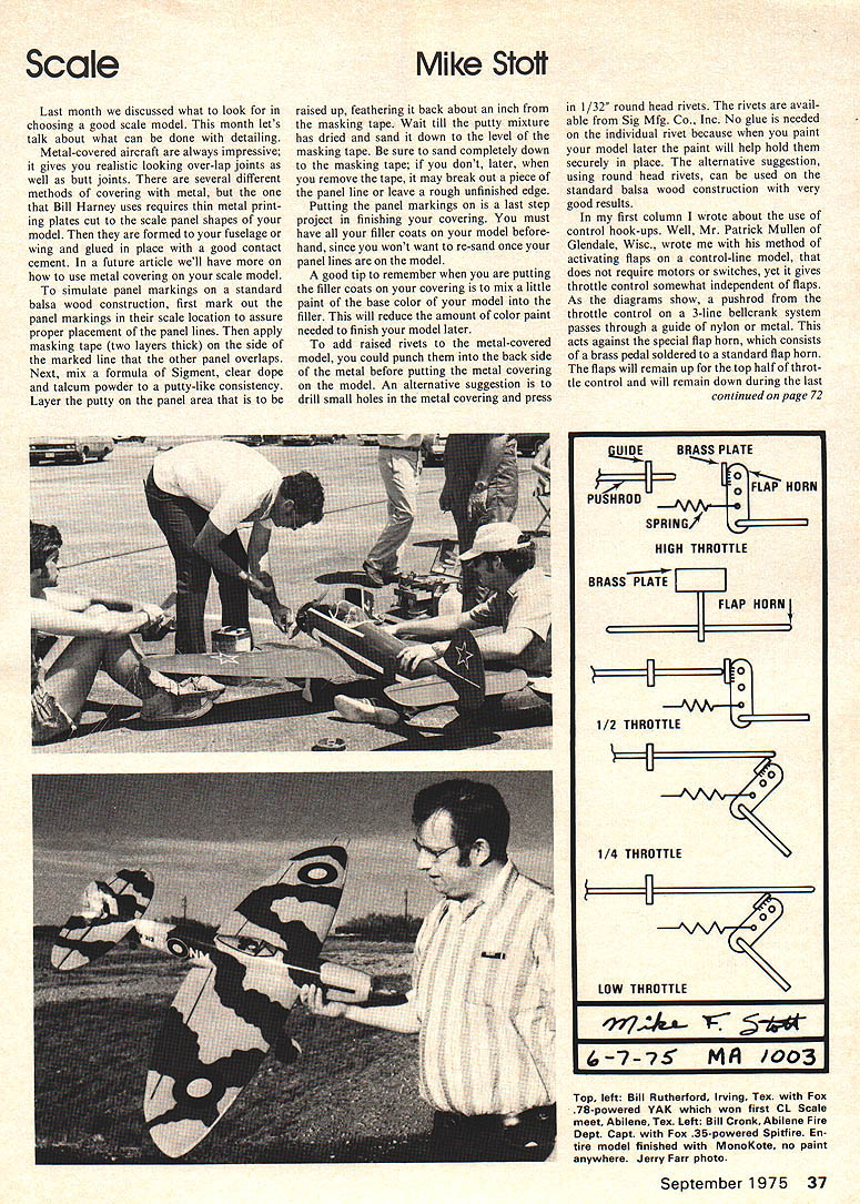
Metal-covered aircraft are always impressive; it gives you realistic looking overlap joints as well as butt joints. There are several different methods of covering with metal, but the one that Bill Harney uses requires thin metal printing plates cut to the scale panel shapes of your model. Then they are formed to your fuselage or wing and glued in place with a good contact cement. In a future article we'll have more on how to use metal covering on your scale model.
To simulate panel markings on a standard balsa wood construction, first mark out the panel markings in their scale location to assure proper placement of the panel lines. Then apply masking tape (two layers thick) on the side of the marked line that the other panel overlaps. Next, mix a formula of Sigment, clear dope and talcum powder to a putty-like consistency. Layer the putty on the panel area that is to be raised up, feathering it back about an inch from the masking tape. Wait till the putty mixture has dried and sand it down to the level of the masking tape. Be sure to sand completely down to the masking tape; if you don't, later, when you remove the tape, it may break out a piece of the panel line or leave a rough unfinished edge.
Putting the panel markings on is a last step project in finishing your covering. You must have all your filler coats on your model beforehand, since you won't want to re-sand once your panel lines are on the model. A good tip to remember when you are putting the filler coats on your covering is to mix a little paint of the base color of your model into the filler. This will reduce the amount of color paint needed to finish your model later.
To add raised rivets to the metal-covered model, you could punch them into the back side of the metal before putting the metal covering on the model. An alternative suggestion is to drill small holes in the metal covering and press in 1/32" round head rivets. The rivets are available from Sig Mfg. Co., Inc. No glue is needed on the individual rivet because when you paint your model later the paint will help hold them securely in place. The alternative suggestion, using round head rivets, can be used on the standard balsa wood construction with very good results.
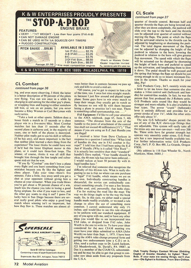
In my first column I wrote about the use of control hook-ups. Well, Mr. Patrick Mullen of Glendale, Wisc., wrote me with this method of activating flaps on a control-line model that does not require motors or switches, yet it gives throttle control somewhat independent of flaps. As the diagrams show, a pushrod throttle control on a 3-line bellcrank system passes through a guide of nylon or metal. This acts against the special flap horn, which consists of a brass pedal soldered to a standard flap horn. The flaps will remain up on the top half of throttle control and will remain down during the last half of throttle.
Between half and quarter throttle the flaps are being lowered and, after they are down completely, the pushrod will slide over the top to the horn and the throttle can be adjusted over quarter of control without moving the flaps. The point at which the flaps will be activated relative to the throttle can be adjusted by lengthening or shortening the pushrod. The total degree movement of the flaps can be adjusted by changing the height of the pushrod in relation to the horn; lowering the pushrod in relation to the horn will give greater flap movement. The speed with which the flaps will be actuated can be changed by shortening the height of both horn and pushrod to speed up the activation, and lengthening them to slow it down. The pedal should be well greased and the spring that brings the flaps up should be just strong enough to do so to insure minimum friction in the system. Thanks so much for your idea, Pat!
G-S Products Corp., Int'l, recently wrote
Control Line: Scale
me a letter to let me know that someone else also makes a 3-line control unit (bellcrank and handle) for control-line models. In fact, he was the person that first produced the J-Roberts unit, as well as the G-S Products units and I think they would be stronger and more reliable. It is also available in four types. The power "crank" (bellcrank) lever is entirely different and provides for power stroke of over 1/4", while the other units effectively are about 3/8". The new G-S bellcranks' shapes permit the use of any of the R/C drive types that are available. They are adjustable. This system will smoothly take all the stress any one man can exert—well over 200 lbs. These units have far greater strength and operate very smoothly under stress. For further information write: G-S Products Corp., Int'l, P. O. Box 488, La Grange, Ore. 97850.
(My address is: 118 East Wheeler St., North Mankato, Minn. 56001.)
Transcribed from original scans by AI. Minor OCR errors may remain.

