
CONTROL LINE SCALE
Bill Boss 77-06 269th Street, New Hyde Park, NY 11040
Introduction
Getting started in Scale was a subject explored in last month's column. As noted then, we will cover in more detail the Competition Regulations, model selection, documentation, static and flight judging, and so on. This month I'll cover the various sets of CL Scale rules and the relationship they have to one another.
CL Scale Events
There are three CL Scale events:
- Precision (formerly called Flying Scale)
- Sport
- Profile
Flying Scale (now Precision) was the only CL Scale event until 1973, when Sport Scale was introduced. Profile was added to the Competition Regulations as a Supplemental event in 1992 because of its popularity around the country.
Rules Structure
Although there are only three events, several sections of rules govern them:
- General Information — All Categories
- Control Line General
- Scale General
- Unified Scale Judging Regulations
Below is how these sections relate to the three events.
#### General Information — All Categories This pertains to all AMA events and competitions and covers:
- Classification of contests and Contest Sanctions
- Contest Director and member responsibilities
- Supplemental and Provisional Rules, and Rules Change Procedures
- Use of metal-bladed propellers, fuels, model identification, model repairs during competition
- Number of models allowed in competition and the Builder of the Model rule
Review this section to understand how these items relate to our Scale events.
#### Control Line General This section is important for CL Scale because it covers:
- Size and type of control handle
- Use and importance of safety thongs
- Size, construction, and measurement of control lines
- Pull tests of the lines
Understanding and following these rules is a top priority for safety — for spectators, pilots, and models.
#### Scale General This section covers rules that generally apply to all CL, RC, and FF Scale events. Key points for CL Scale modelers:
- Applicability
- Paragraph 1 states that unless otherwise specified in an individual event, all rules in this section apply to all Scale events.
- Entry limits and official events
- Paragraph 2: You may enter only one model in each Scale event. It also lists the official AMA Scale events. Note: Profile is not listed as it is classified as a Supplemental event and is not required to be offered at national competitions by AMA.
- Safety Declaration and flight test
- Paragraph 3: Scale modelers must sign a Safety Declaration indicating the model has been test-flown prior to entering competition. CL Scale models must have made an "unassisted" takeoff, flown two laps of level flight, and made a normal landing within the designated flying circle.
- Builder-Flier rule
- The Scale Builder-Flier Rule requires that the builder and flier of a Scale model be the same person. Exception: if the builder cannot fly the model for physical reasons, a proxy may be named. If a proxy is required, be prepared with written evidence to show the Contest Director (see Paragraph 8 of General Information — All Categories).
Other items to note:
- Paragraph 7: Entry of Profile fuselages in the regular Scale events.
- Paragraph 8: Minimum Flight Score, official flight, and the meaning of "airborne".
- Paragraph 9: Prohibition of pyrotechnics in Scale events.
Conclusion
I hope I have sparked your interest in the somewhat dreary subject of rules and that reviewing the sections mentioned above — especially if you are new to Scale — will help you better understand the CL Scale events. Next month we'll cover the Unified Scale Judging Regulations and Precision Scale.
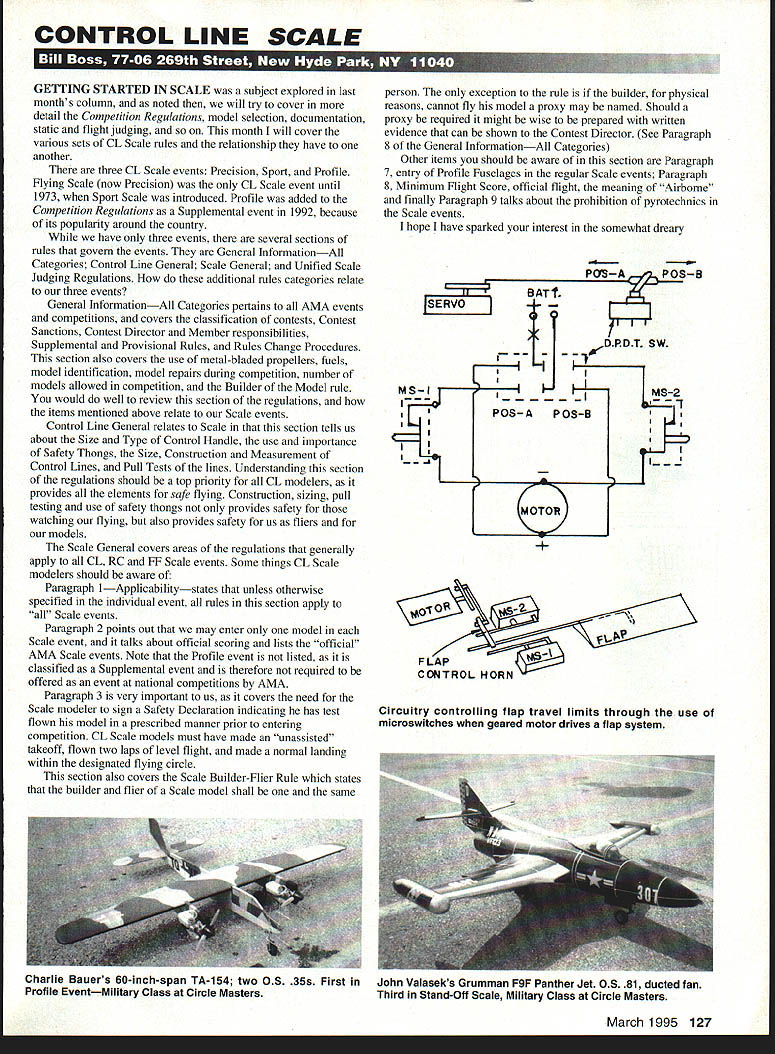
Flap Control System (microswitch and geared-motor arrangement)
Background
Flap control on Jerry Blasczyk's de Havilland Otter was a topic in this column in the November 1994 issue. As a result, I received requests for a copy of the January 1988 column and additional information about using microswitches to control travel limits of flaps and landing gear when driven by a geared motor arrangement rather than a standard servo. The following describes a possible solution and its operation.
Components
- Servo: a normal servo operated by an RC system or an electronic system used by CL fliers.
- DPDT: mini double-pole double-throw toggle switch.
- MS-1 & MS-2: microswitches with normally closed contacts.
- Motor: geared motor drive or a regular servo with the electronics removed.
- Batt: voltage supply sized for the motor's voltage and current requirements.
- Optional single-pole on/off switch shown as "X" in the battery positive path.
System Operation
Starting conditions:
- Flaps in the up position.
- DPDT switch in POS-B.
- MS-2 is operated by the flap control horn (open contacts), stopping current flow to the motor.
To move flaps down:
- Servo moves DPDT switch to POS-A.
- Battery is now connected via MS-1 (closed), allowing the motor to drive the flaps down.
- When the flap control horn engages MS-1, MS-1 opens, cutting off power to the motor and stopping travel — flaps are now down.
To return flaps up:
- Servo moves DPDT switch to POS-B.
- Polarity to the motor is reversed via the DPDT, and the motor drives the flaps up.
- When the flap control horn engages MS-2, MS-2 opens, cutting power and stopping travel — flaps are now up.
Installation Notes and Alternatives
- Microswitches were shown as being operated by the flap control horn, but there are many other possibilities depending on model layout.
- Installation should consider type and size of the model, type of flaps, and space available for the geared motor/servo and microswitches.
- Ensure easy access to components for adjustments and repairs.
Alternatives:
- Use a standard servo (or landing-gear-rated servo) driven by a multichannel electronic system to eliminate the geared motor and microswitches. Servo travel and channel adjustments can provide full up/down motion or incremental control over the full travel.
- The circuitry used by Jerry Blasczyk (January 1988) did not use microswitches but used momentary switch operation at the handle; you can add travel limits by inserting microswitches between the negative side of the batteries and the relay contacts.
Straight CL Application
- A standard 3-line control line modeler can use the geared motor/servo system described above.
- The DPDT switch can be operated by a pushrod linked to the throttle control instead of a servo: full high throttle could move the switch to POS-B (flaps up), low throttle to POS-A (flaps down). This keeps flaps fixed at up or down and unaffected by intermediate throttle changes.
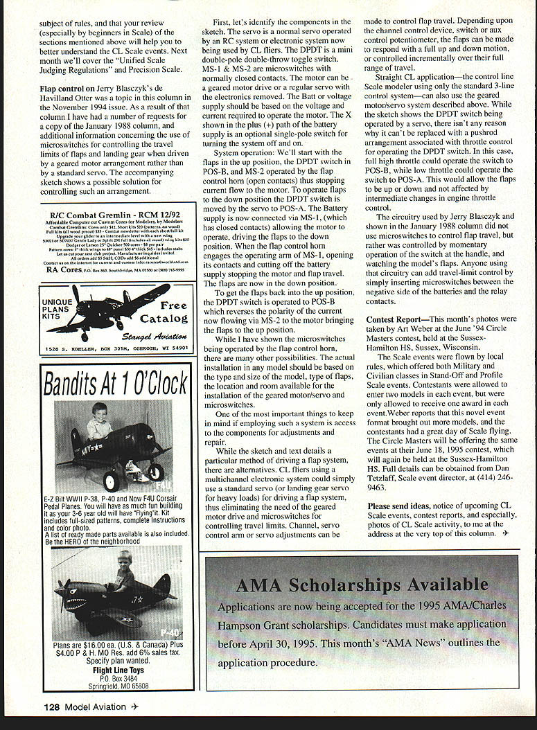
Contest Report
This month's photos were taken by Art Weber at the June 1994 Circle Masters contest, held at Sussex-Hamilton High School, Sussex, Wisconsin.
- Local clubs flew the Scale events, offering both Military and Civilian classes in Stand-Off and Precision Scale events.
- Contestants were allowed to enter two models in each event but could receive only one award in each event. This format brought out more models and provided a great day of flying.
The Circle Masters will offer the same events at their June 18, 1995 contest at Sussex-Hamilton High School. Full details: contact Dan Tetzlaff, Scale event director, at (414) 246-9463.
Please send ideas, upcoming CL Scale event notices, contest reports, and photos of CL Scale activity to the address at the top of this column.
Transcribed from original scans by AI. Minor OCR errors may remain.

