
Control Line: Scale
Mike Gretz
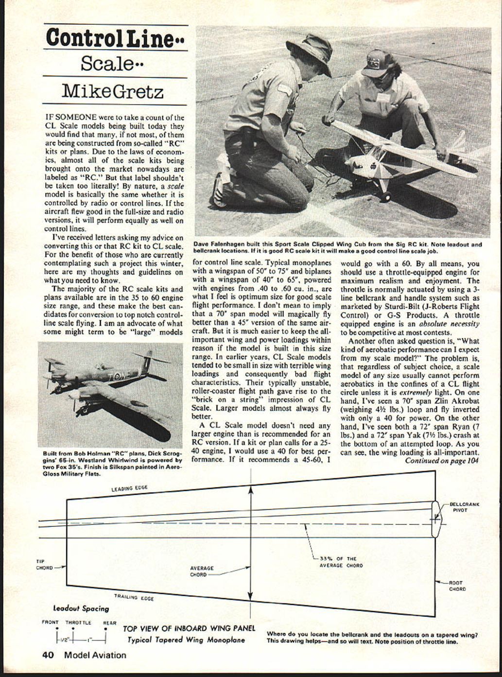
If someone were to count the CL scale models being built today, they would find that many — if not most — are being constructed from so-called "RC" kits or plans. Due to the laws of economics, almost all of the scale kits brought to market nowadays are labeled "RC." That label shouldn't be taken too literally. By nature, a scale model is basically the same whether it is controlled by radio or control lines. If the aircraft flew well in the full-size and radio versions, it will perform equally well on control lines.
I've received letters asking my advice on converting RC kits to CL scale. For the benefit of those contemplating such a project, here are my thoughts and guidelines.
Optimum size and power
- The majority of RC scale kits and plans available are in the .35 to .60 engine-size range; these make the best candidates for conversion to top-notch control-line scale.
- I advocate what some might call "large" models for CL scale:
- Typical monoplanes: 50" to 75" wingspan
- Typical biplanes: 40" to 65" wingspan
- Recommended engines: .40 to .60 cu. in.
- Larger models don't magically fly better than smaller ones of the same subject, but they make it easier to keep wing and power loadings within reason. In earlier years, CL scale models tended to be small with terrible wing loadings and poor flight characteristics — the unstable, roller-coaster flight path that earned the "brick on a string" reputation. Larger models almost always fly better.
A CL scale model doesn't need a larger engine than the RC recommendation. If a kit calls for .25–.40, use a .40 for best performance. If it recommends .45–.60, use a .60. Use a throttle-equipped engine for maximum realism and enjoyment.
- Throttle actuation: normally via a 3-line bellcrank and handle system (examples: Sturdi-Bilt, J-Roberts Flight Control, G-S Products).
- A throttle-equipped engine is essential to be competitive in most contests.
Aerobatic performance
What kind of aerobatics can you expect? It depends largely on wing loading. Regardless of subject, a scale model usually cannot perform much aerobatics in the confines of a CL flight circle unless it is extremely light.
Examples:
- A 70" Zlin Akrobat weighing about 4½ lb looped and flew inverted on a .40.
- A 72" Ryan (7 lb) and a 72" Yak (7½ lb) both crashed trying to complete a loop.
Keep models as light as possible if you want good flight characteristics, and make them even lighter if you hope to do aerobatics.
Control system layout
"Should the bellcrank and leadouts be imbedded in the wing, or mounted mid-fuselage with leadouts projecting out?" It depends on the subject aircraft layout and scale detailing, but here are my preferences and guidelines:
- I prefer mounting the bellcrank inside the fuselage rather than in the wing. This avoids the elevator and throttle pushrod disconnecting from the bellcrank when the wing is removed.
- Leadouts can be located at the wingtip with a plastic, plywood, or wire guide. Make the holes in the guide large enough to allow flexible leadouts to be pulled through and pushed into the fuselage during static judging and transit.
- Locate the fore and aft bellcrank and leadout positions relative to the wing's average chord. This places the control system in direct, traceable relationship to the aircraft's center of gravity and center of pressure and works for most wing shapes (monoplane, biplane, constant chord, tapered, delta, etc.).
- If you can find and draw the average chord on your full-size plan, you can determine the exact control-system locations for your model.
Guidelines:
- Use 33% of the average chord as the rearward limit for the bellcrank position.
- You can move the bellcrank as much as 2" ahead of that point with no ill effects if necessary for cockpit or landing gear details.
- Mount the bellcrank on at least 1/8" thick plywood (use 5-ply, not 3-ply) per the manufacturer's instructions.
- The center of the leadout tray should be on or slightly behind the 33% average chord point.
- Adjustable leadouts are generally unnecessary if located in this general area.
- Spacing between leadouts is not critical; examples range from overlapping to 3/4"–2-1/2". To avoid tangling, space leadouts for a 3-line system as appropriate for your design.
Control surfaces and trimming
- Build separate, movable aileron and rudder surfaces (rather than drawn-on facsimiles) for maximum scale points and full flight trimming.
- Depending on factors, some aileron deflection may be needed to get a model to fly at shoulder height with perfectly level wings.
- Use about 1½ to 2 ounces of outboard wingtip weight.
- The rudder should be offset to the outside of the flight circle, as is standard for most CL models.
- Right engine offset is not normally used in scale models; it's usually difficult to build into the nose without being detectable, and larger scale models typically do not require it as smaller sport models might.
Keep the model light, locate the control system relative to the average chord, and provide full, movable control surfaces for the best chance of successful CL scale flight.
Transcribed from original scans by AI. Minor OCR errors may remain.

