
Control Line: Scale
Mike Gretz
Inevitably, the more expert one becomes at an event, the more he tends to take for granted things that may be puzzling and troublesome for newcomers. The majority of this and last month's columns devote attention to basics that are often overlooked. Some of you experts may get a little bored, but I know from my correspondence that there are people who have fairly basic questions standing between them and their first CL Scale model.
As I mentioned last month, a throttle-equipped engine is an absolute necessity for winning in CL Scale competition. A throttle not only allows you to perform several optional maneuvers (like taxi and touch-and-go) that would otherwise be impossible or, at best, very unrealistic, but it also enables you to perform the basic required maneuvers (takeoff, cruising flight, and landing) with much greater realism and finesse.
Three-line throttle systems
The most common method of operating a throttle-equipped engine in a CL Scale model is with a third control line, in addition to the normal up and down elevator lines. Over the years, ingenious modelers have designed and built their own 3-line throttle systems with mixed results. Some I've seen were as basic (or should I say crude) as simply providing either full-high or full-low throttle with each successive pull of the third control line. Another had the third line spring-loaded to return to low throttle whenever tension was released. You can use your imagination and easily realize that neither of these methods is a very effective step toward realism in flight. What is needed is precise, proportional control of the entire throttle range.
Sturdi-Built Mfg. Co. and G-S Products Corp. both manufacture and market complete 3-line throttle systems designed to do just that. I've used them both, and it would be hard to beat either of these well-designed systems for dependability and precision compared with anything homemade. While there are differences in manufacture between the two brands, they are actually very similar in theory and operation.
The Sturdi-Built product, known as the "J-Roberts Flight Control," has been produced for many years and probably has been used in more CL Scale and Navy Carrier models than all other methods combined. It was the first, and for many years the only, reliable system on the market. The G-S Products 3-line system came out about five or six years ago and has been acknowledged by most Scale and Carrier experts to be an improved version of the older J-Roberts system. It is heavier duty, smoother operating, and has one-third more throttle pushrod movement. I certainly wouldn't hesitate to recommend either brand since I have used both with equally satisfactory results. Both are trustworthy, precision products, and they make what could be a tough job in a CL Scale model very simple.
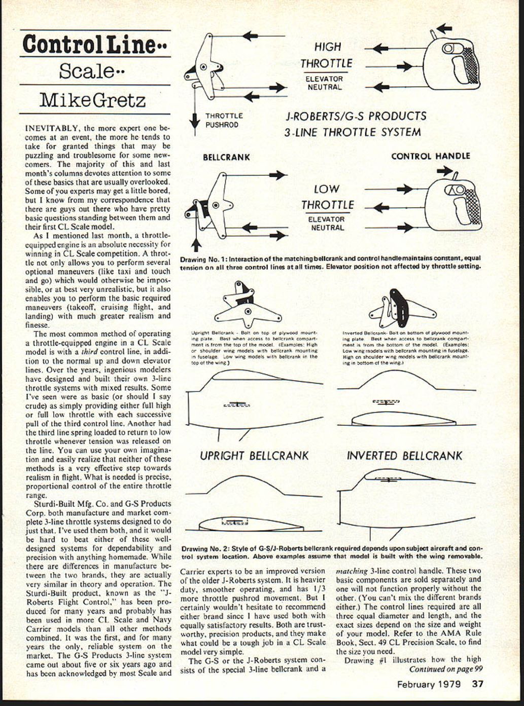
The G-S or J-Roberts system consists of a special 3-line bellcrank and a matching 3-line control handle. These two basic components are sold separately and will not function properly without the other. (You can't mix the different brands either.) The control lines required are all three equal in diameter and length; the exact sizes depend on the size and weight of your model. Refer to the AMA Rule Book, Sect. 49 CL Precision Scale, to find the size you need.
Drawing #1 illustrates how the high-throttle engine position is obtained by movement of the handle's throttle lever forward. As the trigger goes forward, the middle (throttle) control line is drawn toward the control handle while the other two (up and down) lines are extended away from it. The movement of the matching bellcrank pulls in the up-down lines and extends the throttle line toward the handle. The throttle pushrod movement is created in the bellcrank from the interaction of the up-down lines and the throttle line. Thus, equal tension (pull on the lines in flight) is always maintained on all three lines regardless of the throttle position.
Bellcrank types and installation
Both companies offer two basic types of bellcranks, referred to as "Upright" and "Inverted." The style required depends upon the subject aircraft control system location and the general arrangement of your model. Examples and recommended access:
- Upright bellcrank
- Bolt is above the mounting plate.
- Best access from the top of the model.
- Examples: high-shoulder wing models with the bellcrank mounted in the fuselage; low-wing models with the bellcrank mounted in the top of the wing.
- Inverted bellcrank
- Bolt is below the mounting plate.
- Best access from the bottom of the model.
- Examples: low-wing models with the bellcrank mounted in the fuselage; high- or shoulder-wing models with the bellcrank in the bottom of the wing.
Mount the bellcrank on at least 1/8" thick, 5-ply plywood according to the manufacturer's instructions. Pay particular attention to the part about having the slot in the bellcrank mounting plate at 90° to the elevator pushrod. This eliminates undesirable elevator movement in flight as the engine throttle setting is changed. I usually lubricate the bellcrank's moving parts with graphite spray, available in a small tube at most hardware stores.
As with any control system installation, thoroughly check and double-check that there is absolutely no binding or undue friction in the system's operation. It must work perfectly free for best performance. A stiff, balky control system almost always indicates improper installation and can cause special handling problems during low line-tension maneuvers like takeoff, landing, and taxi. Give yourself and your model a chance to perform up to full potential by making sure the control system works easily and smoothly throughout its entire range.
Anecdote: political protest at a contest
Political protest at a model airplane contest sounds ridiculous, doesn't it? But that's what happened last summer. The 1978 RC & CL Scale World Championships were held in conjunction with the 1978 Control Line World Championships (for Stunt, Speed, Team Race) at a common site in Woodvale, England. It sounded great for all parties. But when the countries of Russia, Yugoslavia, Bulgaria, Czechoslovakia, and Poland dropped out of all of the events as a political protest against the entry of South Africa in CL Team Race, the CL Scale World Championships event was fatally affected.
The FAI rules require a minimum of five participating countries to qualify an event as an official "World Championships"—otherwise it is simply an "International" contest. So the withdrawal of the Russian and Polish teams for CL Scale forced its cancellation as a World Championships event at the last minute.
This news reached AMA only days before the U.S. team members were scheduled to depart for England. As travel plans were in motion, models packed, and team spirit high, it was decided to send over the CL Scale team members—Ray Smith, Dan Osdoba, and Roland Baltes—in the still possible hope that an International level competition would be held. But this never materialized.
While I can't help but feel that the boycott was somewhat childish in conception and ineffective, it is all water under the bridge at this point. The Canadians are expected to put in a bid to host the 1980 Scale World Championships in Ottawa. I sincerely hope they will attempt to organize a CL Scale World Championships event as part of the festivities. Under the circumstances, it seems to me that the cancellation of the CL Scale event at Woodvale this year was more a product of the Scale events being tied to the Control Line general World Championships than it was a reflection of current interest in FAI CL Scale. The FAI and the Canadian organizers should remember that the CL Scale event was well attended and strongly contested at all previous Scale World Championships—including 1974 in Lakehurst, New Jersey.
Mike Gretz, Box 162, Montezuma, IA 50171.
Transcribed from original scans by AI. Minor OCR errors may remain.

