
Control Line: Scale
Mike Gretz
Achieving smooth, dependable throttle control over two, three, and even four or more engines is the obvious challenge of multi‑engined scale. (It can be mind‑bending enough at times to get just one engine to idle and accelerate properly!) But no matter how good you are with a carburetor, long before you can even think about making any adjustments, you must construct a reliable system for opening and closing the engine throttles in unison.
The drawings on this page illustrate three of the best and most workable multi‑throttle linkage systems in use. All three are designed to operate from a standard 3‑line G‑S or J‑Roberts bellcrank system. They are flight proven and time tested. Which one is best for your multi‑engined project will depend on your preferences and the dictates of the particular subject aircraft. Below is a close look at each method.
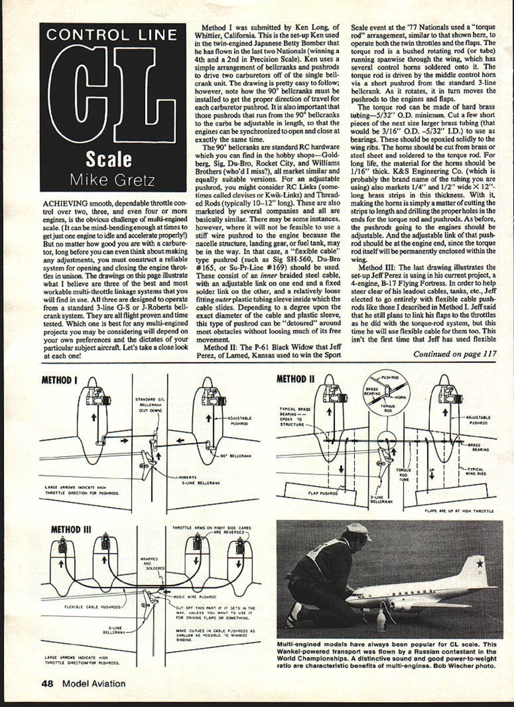
Method I
Submitted by Ken Long, of Whittier, California. This is the set‑up Ken used in the twin‑engined Japanese Betty Bomber that he has flown in the last two Nationals (winning a 4th and a 2nd in Precision Scale).
Ken uses a simple arrangement of bellcranks and pushrods to drive two carburetors off a single bellcrank unit. The drawing is straightforward; however, note how the 90° bellcranks must be installed to get the proper direction of travel for each carburetor pushrod. It is also important that the pushrods that run from the 90° bellcranks to the carbs be adjustable in length so the engines can be synchronized to open and close at exactly the same time.
The 90° bellcranks are standard RC hardware available at hobby shops. Examples of suppliers include:
- Goldberg
- Sig
- Du‑Bro
- Rocket City
- Williams Brothers (who'd I miss?)
For an adjustable pushrod, consider RC links (sometimes called clevises or Kwik‑Links) and threaded rods (typically 10–12 inches long). These are marketed by several companies and are basically similar.
There may be instances where a stiff wire pushrod to the engine is not feasible because the nacelle structure, landing gear, or fuel tank is in the way. In that case, use a "flexible cable" type pushrod (such as Sig SH‑560, Du‑Bro #165, or Su‑Pr‑Line #169). These consist of an inner braided steel cable with an adjustable link on one end and a fixed solder link on the other, and a relatively loose‑fitting outer plastic tubing sleeve inside which the cable slides. Depending on the exact diameter of the cable and plastic sleeve, this type of pushrod can be detoured around most obstacles without losing much of its free movement.
Method II
The P‑61 Black Widow that Jeff Perez of Larned, Kansas used to win the Sport Scale event at the '77 Nationals used a "torque rod" arrangement, similar to the drawing here, to operate both the twin throttles and the flaps.
The torque rod is a bushed rotating rod (or tube) running spanwise through the wing, with several control horns soldered onto it. The torque rod is driven by the middle control horn via a short pushrod from the standard 3‑line bellcrank. As it rotates, it moves the pushrods to the engines and flaps.
Construction notes:
- The torque rod can be made of hard brass tubing—5/32" O.D. minimum.
- Cut a few short pieces of the next size larger brass tubing (3/16" O.D. — 5/32" I.D.) to use as bearings. These should be epoxied solidly to the wing ribs.
- The horns should be cut from brass or steel sheet and soldered to the torque rod. For long life, use material 1/16" thick.
- K&S Engineering Co. markets 1/4" and 1/2" wide x 12" long brass strips in this thickness, which make horn fabrication simple: cut to length and drill the proper holes for the torque rod and pushrods.
As before, the pushrods going to the engines should be adjustable. Place the adjustable link at the engine end, since the torque rod itself will be permanently enclosed within the wing.
Method III
This setup is used by Jeff Perez in his 4‑engine B‑17 Flying Fortress project. To avoid leadout cables, tanks, and other obstructions, Jeff chose to use flexible cable pushrods (as described in Method I) for the throttles and plans to use flexible cable for the flap linkages as well. Jeff used a similar arrangement on the Piper Twin Comanche he flew at last year's Nationals.
Key points for this layout:
- To get all carburetors opening in the same direction, the throttle arms on the right‑side engines need to be reversed to the top of the carb.
- The two braided cables are wrapped and soldered in the center along with a short drive wire which attaches to the bellcrank.
- Note: this drive wire is attached to the same bellcrank arm as the throttle leadout — not in the normal place.
- Du‑Bro threaded couplers are soldered to the carburetor ends of the cables. An RC link is used on this coupler to provide the necessary adjustment to synchronize all engines.
General tips and maintenance
The most important thing with any of these control installations is to eliminate binding and friction wherever possible. The system must operate perfectly free and smooth throughout its entire range for maximum effectiveness and dependability.
During assembly:
- Double‑check that you are not building in a bind.
- If a bind develops, find and cure it before proceeding.
Lubrication:
- Nylon‑to‑metal bearing surfaces generally don't need extra lubrication.
- For metal‑to‑metal surfaces, such as the bellcrank, a little graphite lubricant helps make the system silky smooth.
- Graphite lubricant is available in powder and liquid forms at most hardware stores.
When using flexible cable pushrods (especially long ones), work powdered graphite into the outer plastic sheathing before gluing the pushrod into the model. Hold the sheathed pushrod vertically while applying graphite, or smear the cable itself with powder before sliding it inside the sheathing for best results.
Next month
Next month: coverage of CL Scale at the '79 Nationals!
Mike Gretz Box 162 Montezuma, IA 50171.
Transcribed from original scans by AI. Minor OCR errors may remain.

