
Control Line: Scale
Mike Stott
WHO WOULD THINK a scale modeler would have any problems or worries after he has completed his beautiful scale plane. Well, one of the biggest worries is transporting that model along with assorted flight gear, luggage, kids, and wife to the site of the contest. If you are fortunate enough to own a van, or better yet a motor home, the problem is somewhat less complex. But the majority of us, along with myself, have to contend with getting everything we need in an average sized car. Sometimes it is just impossible to fit your scale model in its entirety into even a regular sized car. The most logical solution is to find a way to remove the wings. I'm offering some suggestions on the matter since I run into this problem quite often, and I hope they can help you out.
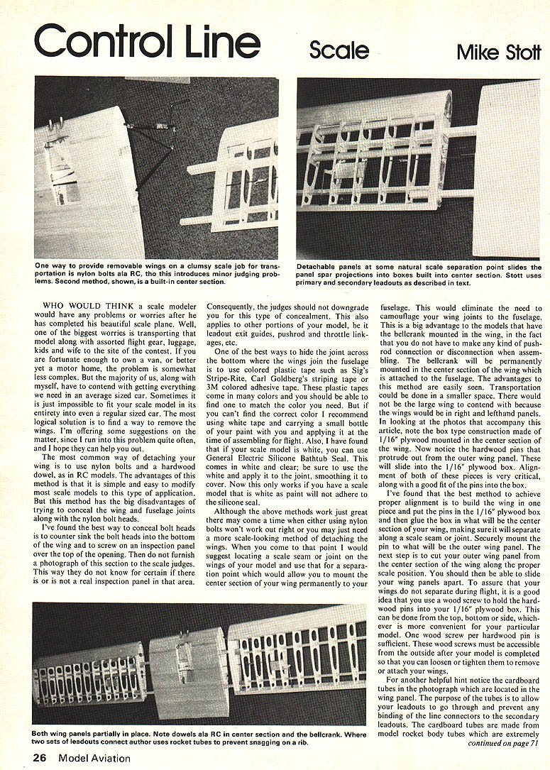
The most common way of detaching your wing is to use nylon bolts and a hardwood dowel, as in RC models. The advantages of this method is that it is simple and easy to modify most scale models to this type of application. But this method has the big disadvantages of trying to conceal the wing and fuselage joints along with the nylon bolt heads.
I've found the best way to conceal bolt heads is to countersink the bolt heads into the bottom of the wing and to screw on an inspection panel over the top of the opening. Then do not furnish a photograph of this section to the scale judges. This way they do not know for certain if there is or is not a real inspection panel in that area. Consequently, the judges should not downgrade you for this type of concealment. This also applies to other portions of your model, be it leadout exit guides, pushrod and throttle linkages, etc.
One of the best ways to hide the joint across the bottom where the wings join the fuselage is to use colored plastic tape such as Sig's Stripe-Rite, Carl Goldberg's striping tape or 3M colored adhesive tape. These plastic tapes come in many colors and you should be able to find one to match the color you need. But if you can't find the correct color I recommend using white tape and carrying a small bottle of your paint with you and applying it at the time of assembling for flight. Also, I have found that if your scale model is white, you can use General Electric Silicone Bathtub Seal. This comes in white and clear; be sure to use the white and apply it to the joint, smoothing it to cover. Now this only works if you have a scale model that is white as paint will not adhere to the silicone seal.
Although the above methods work just great there may come a time when either using nylon bolts won't work out right or you just need a more scale-looking method of detaching the wings. When you come to that point I would suggest locating a scale seam or joint in the wings of your model and use that for a separation point which would allow you to mount the center section of your wing permanently to your fuselage. This would eliminate the need to camouflage your wing joints to the fuselage. This is a big advantage to models that have the bellcrank mounted in the wing, in the fact that you do not have to make any kind of pushrod connection or disconnection when assembling. The bellcrank will be permanently mounted in the center section of the wing which is attached to the fuselage. The advantages to this method are easily seen. Transportation could be done in a smaller space. There would not be the large wing to contend with because the wings would be right and left-hand panels.
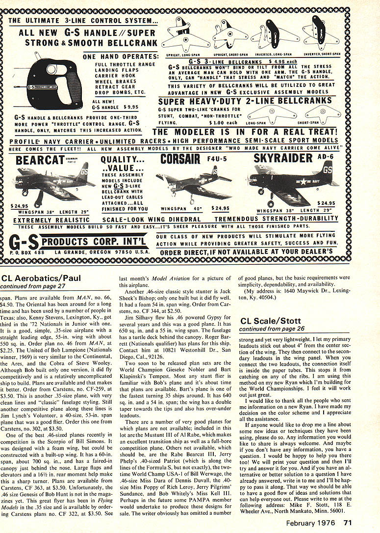
In looking at the photos that accompany this article, note the box type construction made 1/16" plywood mounted center section wing. Now notice the hardwood pins that protrude out from the outer wing panel. These will slide into the 1/16" plywood box. Alignment of both of these pieces is very critical, along with a good fit of the pins to the box.
I've found the best method to achieve proper alignment is to build the center section wing, put the pins in the 1/16" plywood box, and glue the box to what will be the center section wing making sure it will separate along the scale seam joint. Securely mount the pins that will be in the outer wing panel. The next step is to cut the outer wing panel from the center section wing along the proper scale position. The outer wing panels should be able to slide apart. To assure the wings separate during flight it is a good idea to use wood screws to hold the hardwood pins into the 1/16" plywood box. This can be done from the top, bottom or side, whichever is more convenient for your particular model. One wood screw per hardwood pin is sufficient. These wood screws must be accessible from the outside after your model is completed so that you can loosen or tighten them to remove or attach your wings.
Another helpful hint: notice the cardboard tubes in the photograph which are located in the wing panels. The purpose of the tubes is to allow your leadouts to go through and prevent any binding of the line connectors to the secondary leadouts. The cardboard tubes are made from model rocket body tubes which are extremely lightweight and yet very flexible. I let my primary leadouts stick out about 1" from the center section of the wing. They then connect to the secondary leadouts in the wing panel. When you connect the two leadouts, the connection itself is inside the paper tubes in the tips of the wing. This stops it from catching on any of the ribs. I am using this method on my new Ryan which I'm building for the World Championships. I feel it will work just great.
I would like to thank all the people who sent me information on a new Ryan. I have made my decision on the color scheme and I appreciate all the assistance.
If anyone would like to drop me a line about some new ideas or techniques they have been using, please do so. Any information you would like to share is always welcome. And maybe if you have anything you would like to have me print I would be happy to have it. I will print your question and then I'll try and answer it for you and if you have an alternative or better solution to a question I have already answered, write to me and I'll be happy to pass it along. That way we should be able to have a good flow of ideas and solutions that can help everyone out. Please write to me at the following address: Mike F. Stott, 118 E. Wheeler Ave., North Mankato, Minn. 56001.
Transcribed from original scans by AI. Minor OCR errors may remain.

