
Control Line: Scale
Dick Byron
Last month's column gave information from Richard H. Burkett of Manassas Park, VA, pertaining to scale information available from the Cartographic Division of the National Archives. The complete address is: National Archives, Cartographic Division, Pennsylvania Avenue & 8th Street N.W., Washington, DC 20408, telephone (202) 523-3062. This should end any confusion on where to get this data.
Control mechanism
If you remember, last month we discussed the control-handle mechanism I used with the A6M5C Zero to actuate the flaps. This month we will discuss the airplane's internal mechanism, which is the heart of the system.
The pictures show views from the right and left sides of the mechanism as installed in the wing of the aircraft. The two blocks at the forward portion of the unit act as guides for the leader wire that is installed on a brass drum on the front of the mechanism. The rod through the center is 1/4-in. brass. The unit is mounted in a U-shaped brass mount and held securely in place on the wing with epoxy.
The aft portion of the mechanism resembles a worm gear. It is actually a large spring expanded to form a screw mechanism, with a washer soldered on the front to prevent forward movement of the follower past the maximum up-point of the flaps. The follower surrounding the spring has a brass tube soldered beneath it which holds the piano wire that connects to the flap horns. I use an RC strip aileron control horn to connect directly to the flaps through the wing.
A C-shaped piece of piano wire passes over the foremost portion of the follower and goes through the brass-tube follower; the little protrusions follow the worm gear as it is turned, making the control mechanism move to the rear as the worm gear is turned by pulling on the appropriate control cable.
The system took several hours to work out and to produce. It performs extremely well and has minimal cost. Drawings would be more confusing than pictures; I will be happy to show this system to anybody interested at the Nats this coming summer. I use .008-in. control cable from the handle to the aircraft to actuate the system, thereby reducing the drag which additional lines contribute to the airplane's performance.
Control Line Scale World Championships, 1982
With the offer by the USSR to hold the 1982 Scale World Championships, we may finally have a CL Scale World Championship again, after the last two championships omitted this event. I understand that the last championships in Ottawa, Canada, could have held the event, but administrators elected not to do so. This bit of information was given to me by a Canadian CL Scale flier; I do not have other information to corroborate it. If true, it is a shame that it happened. The time put into building a museum-quality scale aircraft, only to have it not be able to compete in the World Championships, is very disappointing to contestants and spectators alike.
(Editor's note: CL Scale was canceled from the 1980 Scale Championships in Canada when five countries had not entered the CL event by the organizer's deadline. An event cannot be classified as a World Championship unless five or more countries enter.)
Aircraft of the past
The other picture this month is of a model built by a new friend who is an old-time CL Scale flier, Bill Howard of Waterloo, IA. Bill was a member of the United States Air Force team in the early '60s, and his home is now a mandatory stop on my travels into Waterloo. We just visit and talk about the old times. I asked Bill for some pictures of some of the aircraft he competed with back then, and I have decided to include one in the column because it means a lot to many flyers—not only the aircraft, but the advances that have been made in the event in the last 20 years.
P-47N (circa 1960)
One model (not shown) is a P-47N from an old Berkeley kit, built in 1960. It had working flaps, lights, an electrical sliding canopy, bomb drop, cowl flaps that opened and closed, and shock-absorbing landing gear. It was powered with a Fox .35 with a Bramco throttle, weighed approximately four pounds, and competed in the Air Force Championships in Japan in the early '60s.
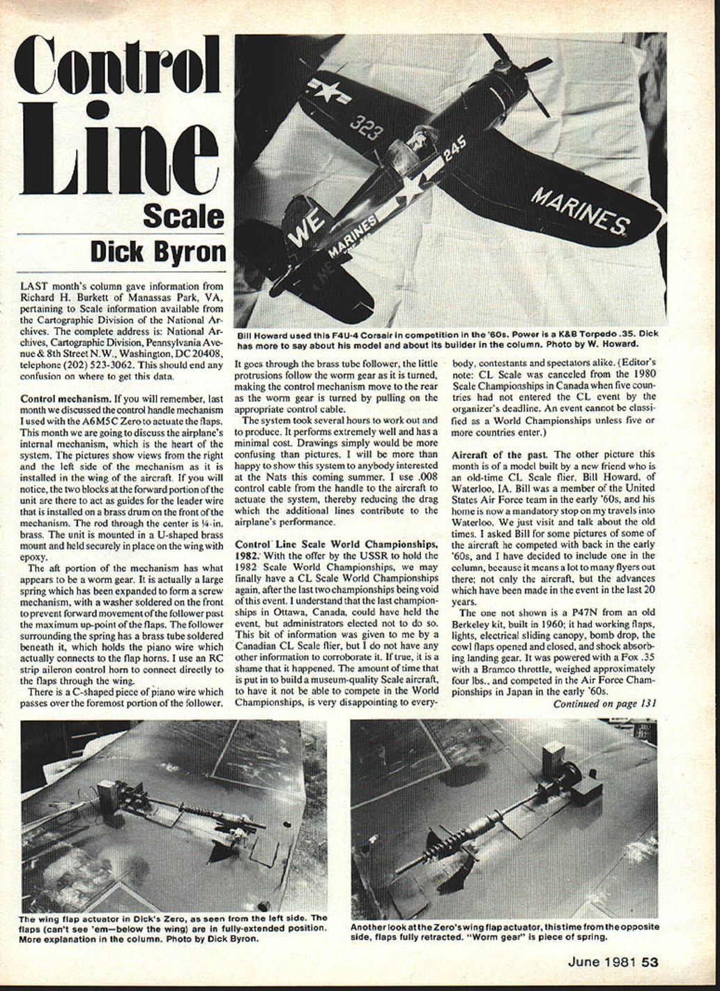
F4U-4 Corsair (circa 1963)
The other aircraft Bill competed with is an F4U-4 Corsair from Super Scale drawings, built about 1963. It was powered with a Torpedo .35 and built to 3/8-in. or one-in. scale. It had a Bramco throttle, working lights, working cowl flaps, and a scale arresting hook. The aircraft was painted with Aero Gloss paint and weighed approximately three pounds.
Bill is an old-time modeler whom we may be able to convince to compete again. His skills are quite obvious. He currently runs Bill Howard's Hobby Shop in Waterloo, IA, and is always happy to discuss things old and new alike. I find Bill to be a very enjoyable person to visit.
Anyone reading this column who has older pictures, please send them in! We would all enjoy reminiscing, and we also like to see the latest work. We will try to use every piece of information we get.
Remaining details
- If the canopy wasn't glued on earlier, glue it on now (after the paint has dried). Mark the canopy frame lines using a marking pen.
- Cut and bend to shape 1/16-in. dia. wire for the pushrod, landing gear, and wire skid. Poke the skid up through the wing into the right fuselage side at the angle shown. Glue it into its hole with epoxy.
- Install the bellcrank, pushrod, and elevator horn. I strongly recommend the use of the Carl Goldberg 1/2 A nylon bellcrank and horn set.
- Flex the elevator up and down a number of times to loosen it up after painting. If the pushrod bows too much when applying up control, bend a pushrod guide out of 1/16-in. dia. wire and glue it in place. Mine didn't need one.
- Attach the wheels to the wire landing gear using a glob of 5-minute epoxy and a paper washer.
- Mark the position of the engine mounting screws, make the screw holes (I use wood screws), and install the engine. Before tightening it down, slide in the landing-gear wire, then tighten the engine mounting screws.
- Install the lead-outs, and you're finished.
Flying tips
For most types of flying and wind conditions, I recommend 35-ft. wire lines of .008-in. dia. On takeoff, avoid giving the plane up-control, since it will rise off the ground by itself when it reaches flying speed because of the lifting airfoil. When the engine stops, you will have a long, gentle landing glide—provided you don't try to keep climbing. If you are overly nervous at first, let it bash into the ground a time or two. Pick it up, dust it off, start the engine, and try again.
Finishing hints
I have been experimenting with a new primer to decrease the finishing weight of an aircraft. It is made using Sig microballoons and lightweight dope, thinned with Sig thinner. It sprays easily and does fill larger-grained woods. The aircraft I primed with this filler would normally take eight hours to sand out; it took one hour and ten minutes to sand to the same ready-for-clear-dope condition. While not working as well as talcum powder, this primer appears workable in place of talcum powder where weight is a significant factor. This could probably save two or three ounces on any given medium-sized aircraft. Some people may find this doesn't work to their satisfaction; however, I feel it is worth experimenting with. It could possibly save an overall five or six ounces on an aircraft, because the predominant amount of paint is applied to the rear of the center of gravity.
If you have other finishing techniques, please feel free to submit them for publication.
Closing / Contact
Please send pictures, sketches, and ideas for publication—we need a good input from everybody to perpetuate our love for scale modeling.
Send information to: Richard Byron 2506 So. 161st Circle Omaha, NE 68130
Transcribed from original scans by AI. Minor OCR errors may remain.

