
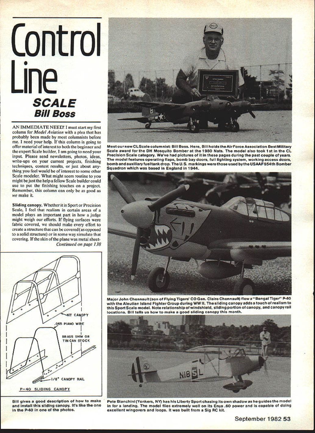
Control Line: SCALE
Bill Boss
I must start my first column for Model Aviation with a plea that has probably been made by most columnists before me. I need your help. If this column is going to offer material of interest to both the beginner and the expert Scale builder, I am going to need your input. Please send newsletters, photos, ideas, write-ups on your current projects, finishing techniques, contest results, or just about anything you feel would be of interest to some other Scale modeler. What might seem routine to you might be just the help a fellow Scale builder could use to put the finishing touches on a project. Remember, this column can only be as good as we make it.
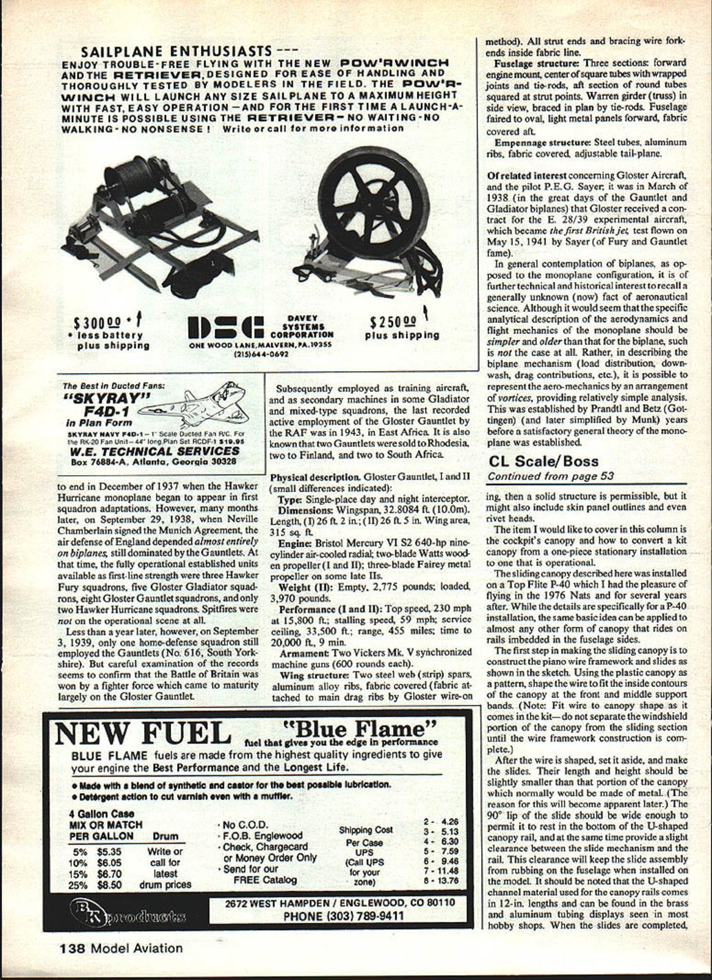
Sliding canopy
Whether it is Sport or Precision Scale, realism in certain areas of a model plays an important part in how a judge might weigh our efforts. If flying surfaces were fabric covered, we should make every effort to create a structure that can be covered (as opposed to a solid structure) or in some way simulate that covering. If the skin of the plane was metal sheet, then a solid structure is permissible, but it might also include skin panel outlines and even rivet heads.
The item I would like to cover in this column is the cockpit canopy and how to convert a kit canopy from a one-piece stationary installation to one that is operational.
The sliding canopy described here was installed on a Top Flite P-40 which I had the pleasure of flying in the 1976 Nats and for several years after. While the details are specifically for a P-40 installation, the same basic idea can be applied to almost any other form of canopy that rides on rails embedded in the fuselage sides.
The first step in making the sliding canopy is to construct the piano-wire framework and slides as shown in the sketch. Using the plastic canopy as a pattern, shape the wire to fit the inside contours of the canopy at the front and middle support bands. Note: fit the wire to the canopy shape as it comes in the kit — do not separate the windshield portion of the canopy from the sliding section until the wire framework construction is complete.
After the wire is shaped, set it aside and make the slides. Their length and height should be slightly smaller than that portion of the canopy which normally would be made of metal (the reason for this will become apparent later). The 90° lip of the slide should be wide enough to permit it to rest in the bottom of the U-shaped canopy rail, and at the same time provide a slight clearance between the slide mechanism and the rail. This clearance will keep the slide assembly from rubbing on the fuselage when installed on the model.
The U-shaped channel material used for the canopy rails comes in 12-in. lengths and can be found in the brass and aluminum tubing displays seen in most hobby shops. When the slides are completed, solder the wire frames to the slides.
After the framework is finished, check the shape again by placing the assembly inside the canopy, and when the fit is good, the windshield and sliding sections can be separated. Now position the framework inside the sliding section, and carefully drill small holes as shown in the sketch to accept 1/32-in. rivets. Complete the job by riveting the plastic canopy to the wire framework.
What do you do about the metal framework showing through the clear plastic? You can paint the metal-structure outlines, or cover them with aluminum tape for a more realistic appearance. The tape used on this canopy was Arno Aluminum Adhesive Tape, which comes in rolls 2 in. wide by 10 yd. long. It has a paper-like backing that protects the adhesive until ready for use. The backing also allows free handling of the tape while it is being cut to the desired shape. The tape may be purchased in most local hardware stores.
If you decide to use the aluminum tape procedure rather than painting, cut strips of the tape to appropriate widths with an X-Acto knife or scissors and apply them to the canopy. When cutting strips for the canopy edges, allow a little extra width so that the tape can be rolled around the edge and onto the inside of the canopy. If you wish to paint the tape, rub its surface slightly with 200–400 grit sandpaper before cutting the tape into its proper sizes. Set the completed sliding section aside.
The next step is to install the windshield section of the canopy in its appropriate place on the fuselage. When that is completed, cut two lengths of the U-shaped channel that will now be installed in the fuselage sides. Be sure the rails are long enough to permit full opening of the canopy, and that they are positioned in the fuselage correctly, permitting a perfect alignment when the sliding section meets the windshield in the closed position. After the windshield and rails have been installed, spread the sliding section slightly and let it snap into the rails.
Your completed canopy should have the metal-construction look with the rivets and wire framework hidden from view and should also add a bit more realism to your model.
Don't forget — send material to Bill Boss, 77-06 269th Street, New Hyde Park, NY 11040.
Transcribed from original scans by AI. Minor OCR errors may remain.

