
Control Line: Scale
Bill Boss
Back to basics
That is what my predecessor, Dick Byron, stated was a major goal of his for this CL Scale column. I, too, would like to follow that same theme from time to time. In Dick's last column (August 1982) he briefly covered several items that should be considered by a new Scale builder: engine cooling, selection of a model, line sweepback, and mounting the bellcrank for the conversion of an RC Scale kit to CL — the item I will discuss here.
RC to CL conversion
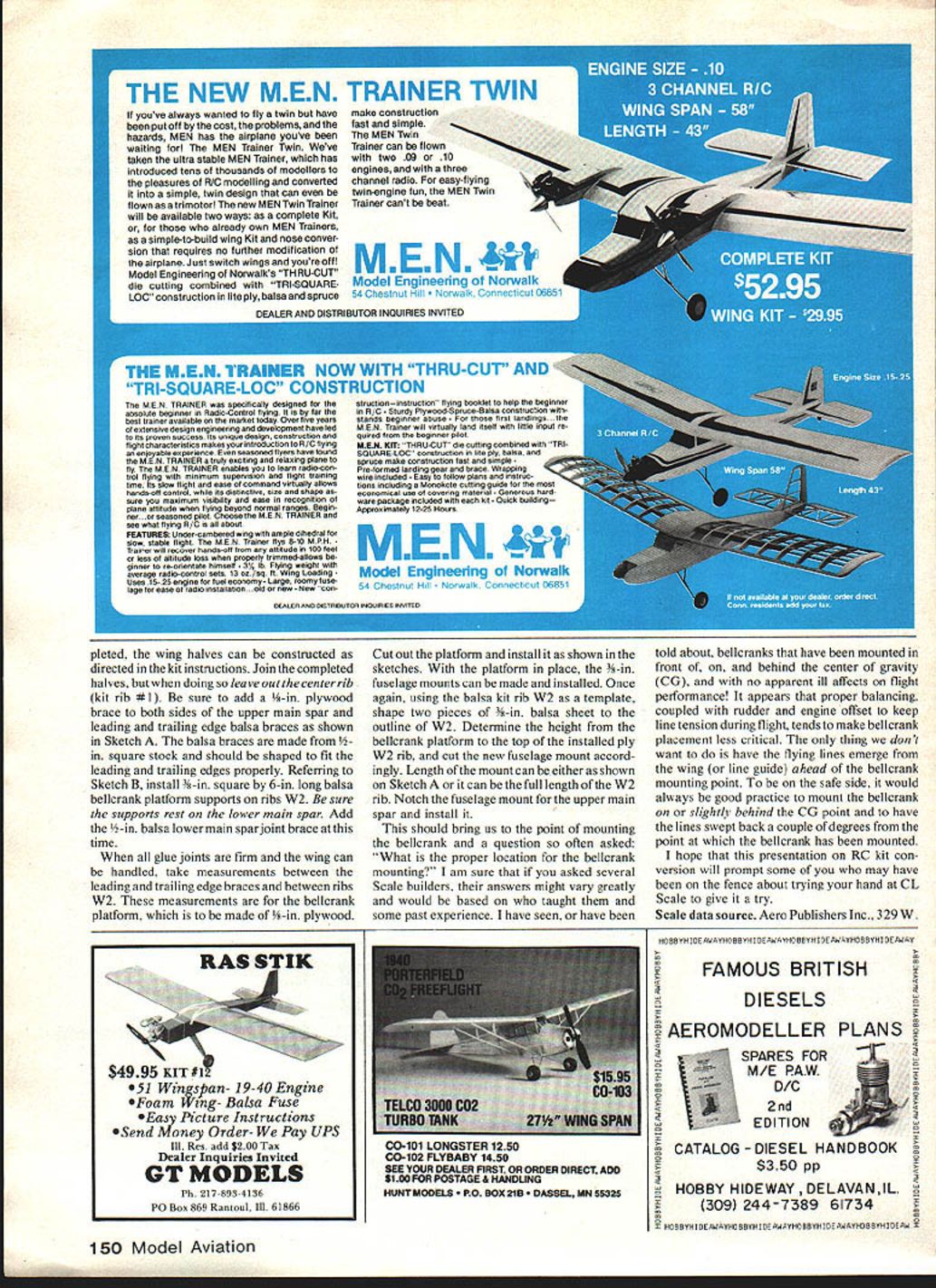
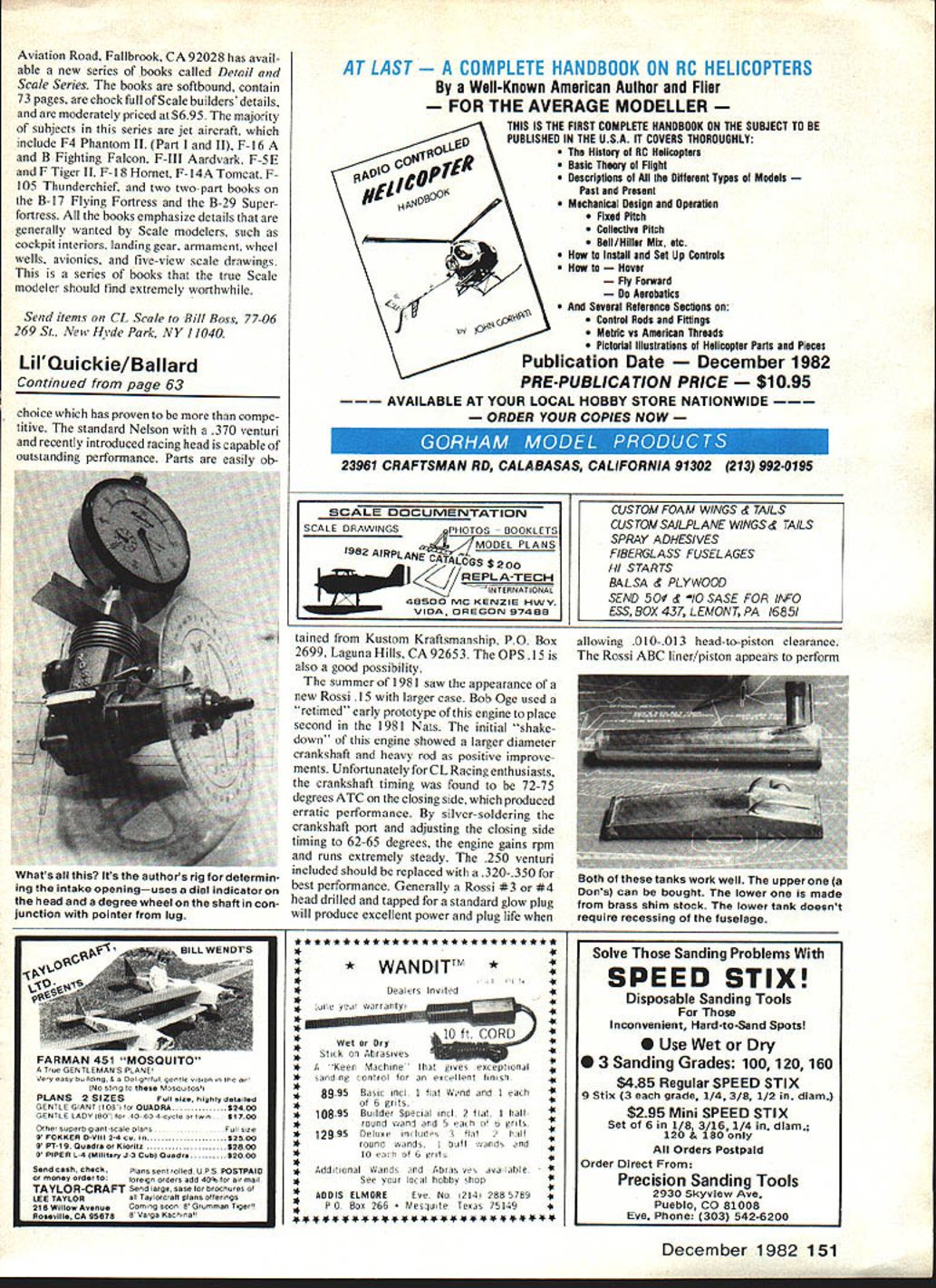
The most obvious question is where and how to mount the bellcrank. In most RC models, the wing area where we would normally mount the bellcrank is usually reserved for servos, batteries, or receiver equipment. Therefore, the structure of this wing area requires considerable modification to make it suitable for control-line flying.
This area of the wing also needs strengthening for two additional reasons:
- To withstand the control-system pull tests, which, depending on the model's weight, can be as high as 80 lb. (Specific pull-test requirements for all CL Scale models can be found in the AMA rule book under Section 52-A, CL Precision Scale.)
- To withstand the extra stresses imposed on the landing gear and its mounting during takeoff and landing of the CL model, which are considerably different from those of the RC version. During RC landings, the landing gear is stressed mainly by a straight-ahead course. During a CL landing, the gear is confined by the flying wires to a circular path, producing extreme sideways stress on the gear and its mount.
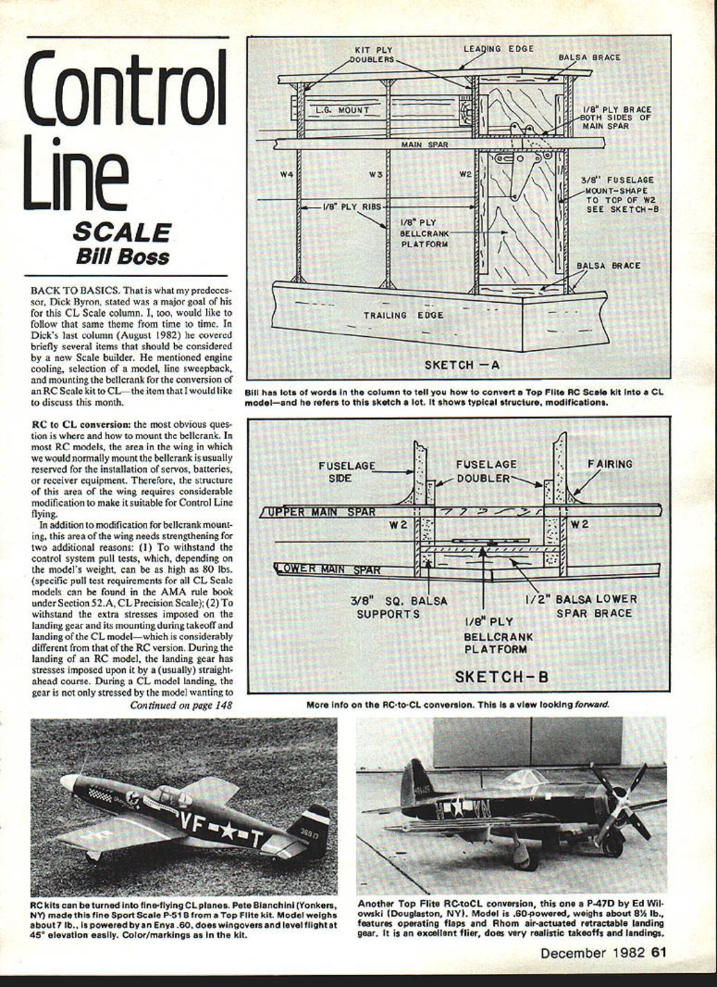
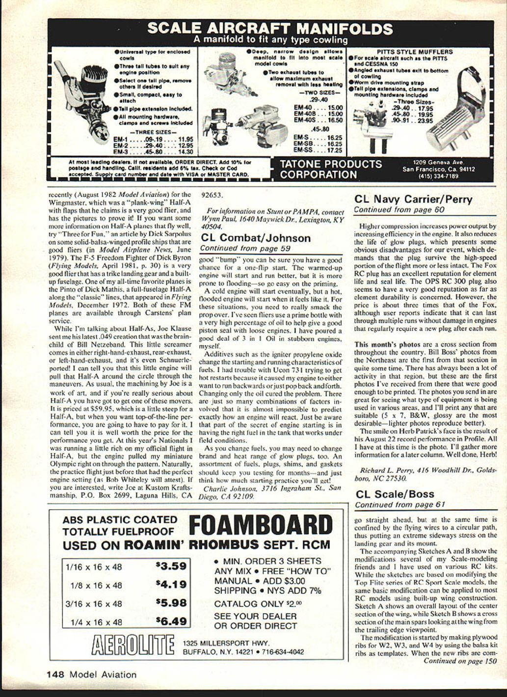
The accompanying Sketches A and B show the modifications several of my Scale-modeling friends and I have used on various RC kits. While the sketches are based on modifying the Top Flite series of RC Sport Scale kits, the same basic modification can be applied to most RC models using built-up wing construction. Sketch A shows an overall layout of the wing center section; Sketch B shows a cross section of the main spars as viewed from the trailing edge.
Modification steps (overview):
- Make plywood ribs for W2, W3, and W4 using the balsa kit ribs as templates.
- Assemble the center section and fit the bellcrank platform to the top of W2 (see Sketch B).
- Fit a plywood brace under the bellcrank platform to the fuselage top or to the wing-bolt web to help distribute loads.
- Add plywood doublers to the main spar in the bellcrank area.
- Use a maple or other hardwood plate to mount the landing gear; through-bolt it to the wing structure.
- Add fillets and triangulation where required to eliminate flex and spread loads.
When completed, construct the wing halves as directed in the kit instructions. Join the completed halves, but leave out the center rib (kit rib #1). Be sure to add a 3/8-in. plywood brace to both sides of the upper main spar and leading- and trailing-edge balsa braces as shown in Sketch A. The balsa braces are made from 1/2-in. square stock and should be shaped to fit the leading and trailing edges properly.
Referring to Sketch B, install 3/8-in. square, 6-in. long balsa bellcrank-platform supports on ribs W2. Be sure the supports rest on the lower main spar. Add the 1/4-in. balsa lower main-spar joint brace at this time.
When all glue joints are firm and the wing can be handled, take measurements between the leading- and trailing-edge braces and between ribs W2. These measurements are for the bellcrank platform, which is to be made of 1/8-in. plywood. Cut out the platform and install it as shown in the sketches.
With the platform in place, make and install the 3/16-in. fuselage mounts. Using the balsa kit rib W2 as a template, shape two pieces of 3/16-in. balsa sheet to the outline of W2. Determine the height from the bellcrank platform to the top of the installed ply W2 rib and cut the new fuselage mount accordingly. Length of the mount can be either as shown on Sketch A or the full length of the W2 rib. Notch the fuselage mount for the upper main spar and install it.
Bellcrank placement A common question is, "What is the proper location for the bellcrank mounting?" Answers vary among builders and are often based on who taught them or past experience. I have seen—or been told about—bellcranks mounted in front of, on, and behind the center of gravity (CG), often with no apparent ill effects on flight performance. Proper balance coupled with rudder and engine offset to keep line tension during flight tends to make bellcrank placement less critical.
Two practical rules:
- Do not have the flying lines emerge from the wing (or line guide) ahead of the bellcrank mounting point.
- To be safe, mount the bellcrank on or slightly behind the CG and have the lines swept back a couple of degrees from the bellcrank mounting point.
I hope this presentation on RC kit conversion will prompt some of you who have been on the fence about trying CL Scale to give it a try.
Scale data source
Aero Publishers Inc., 329 W. Aviation Road, Fallbrook, CA 92028, has available a new series called the Detail and Scale Series. The books are softbound, 73 pages, chock-full of scale-builder details, and reasonably priced at $6.95. Most titles are jet aircraft and include:
- F-4 Phantom II (Part I and II)
- F-16A and B Fighting Falcon
- F-111 Aardvark
- F-5E and F Tiger II
- F-18 Hornet
- F-14A Tomcat
- F-105 Thunderchief
- Two two-part books on the B-17 Flying Fortress and the B-29 Superfortress
All the books emphasize details generally wanted by scale modelers, such as cockpit interiors, landing gear, armament, wheel wells, avionics, and five-view scale drawings. This is a series that the serious scale modeler should find extremely worthwhile.
Send items on CL Scale to: Bill Boss 77-06 269 St. New Hyde Park, NY 11040
Transcribed from original scans by AI. Minor OCR errors may remain.

