
Control Line: SCALE
Bill Boss
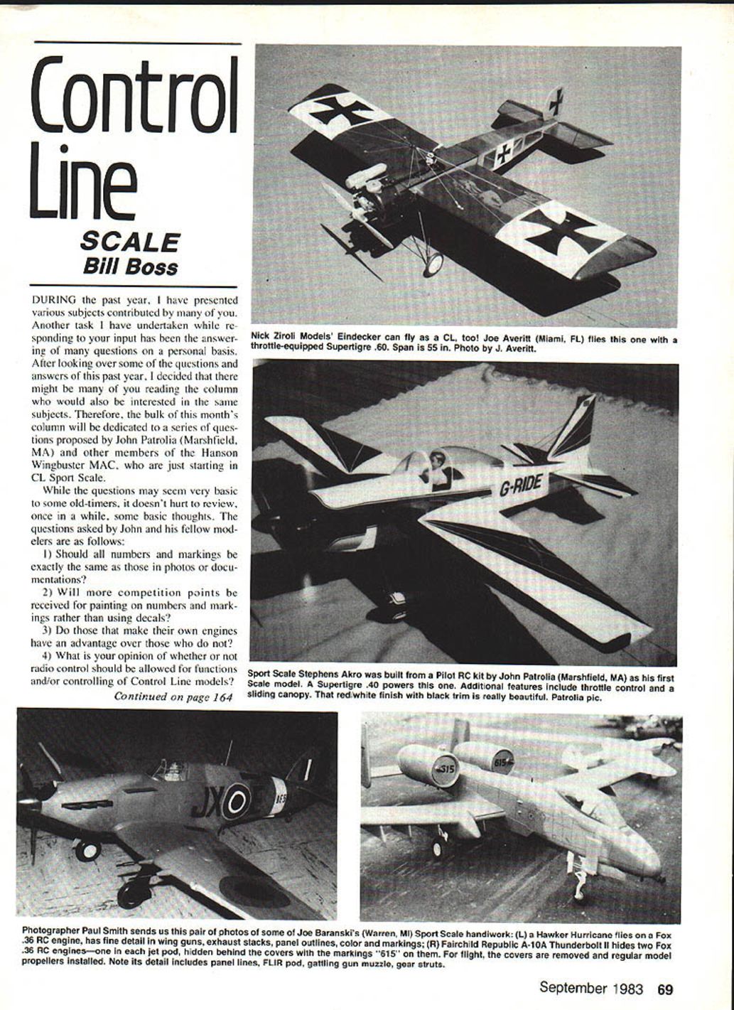
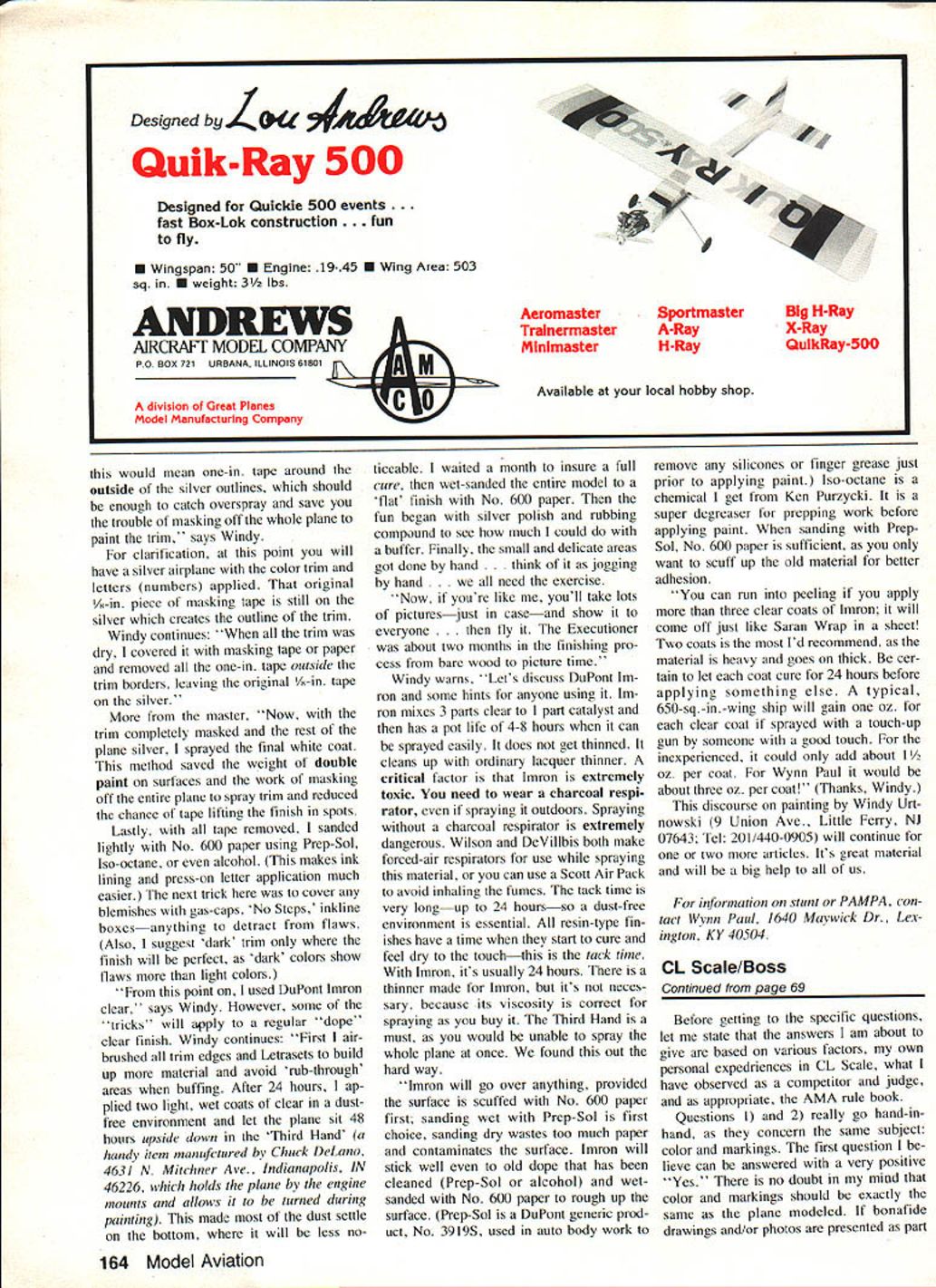
During the past year I have presented various subjects contributed by many of you. Another task I have undertaken while responding to your input has been answering many questions on a personal basis. After looking over some of the questions and answers of the past year, I decided that there might be many readers of the column who would be interested in the same subjects. Therefore, the bulk of this month's column is dedicated to a series of questions proposed by John Patrolia (Marshfield, MA) and other members of the Hanson Wingbuster MAC, who are just starting in CL Sport Scale.
The questions asked by John and his fellow modelers are as follows:
- Should all numbers and markings be exactly the same as those in photos or documentation?
- Will more competition points be received for painting on numbers and markings rather than using decals?
- Do those who make their own engines have an advantage over those who do not?
- What is your opinion of whether or not radio control should be allowed for functions and/or controlling of Control Line models?
CL Scale / Boss
Before answering the specific questions, let me state that the answers below are based on various factors: my personal experience in CL Scale, what I have observed as a competitor and judge, and, as appropriate, the AMA rule book.
Answer to Questions 1 and 2 (Color and Markings)
- Should markings match photos/documentation? Yes. Color and markings should match the plans and/or photographs of the prototype whenever possible. Where exact duplication is not practical, the modeler’s intent should be considered; if the model reproduces the prototype’s appearance in spirit and general detail it should be rewarded.
- If you deviate from the documented color/markings, it is your responsibility to provide appropriate written description or other evidence to substantiate the choices applied to the model. Don’t forget: it is the competitor’s responsibility to provide proof-of-scale documentation. Judges should not have to guess at your reasons.
- Painting vs. decals: This depends on the Scale category—Sport or Precision.
- Precision Scale: Painting numbers and insignia is effectively a must to obtain maximum points in the “Color and Markings” category, because judges inspect details closely and require true fidelity to scale.
- Sport Scale: Models are judged from a distance of 15 ft and no detailed pre-judging inspection is permitted. If decals of proper size and color are available and are applied neatly, they should be acceptable—judges at the prescribed distance should not be able to detect decal use. If suitable decals cannot be found, painting all markings is the safer route.
- In general: what counts is the end result. Neatly and accurately hand-painted markings demonstrate craftsmanship and are credited. Neatly applied, accurate decals should not be penalized. Poorly executed hand-painted markings will be judged more harshly than properly applied decals.
Answer to Question 3 (Home-built engines)
- Those who make their own engines may have a slight advantage only insofar as they can tune and tailor the engine to a particular model. Commercially produced engines, when properly installed and tuned, are equally capable in competition.
- The important points are reliable, appropriate power and proper mounting and cowling to simulate the prototype.
- AMA Sport and Precision Scale rules do not provide extra points for making your own engine. In FAI Scale events there is an ingenuity category where extraordinary construction (such as making your own engine) can be awarded points.
Answer to Question 4 (Radio control for functions)
- The AMA rule book (General Control Line, Section 22, Paragraph 2) states that "manipulation of control surfaces may be accomplished by the normal control line handle, or by electrical impulses transmitted through the lines."
- My interpretation: radio control as normally applied (transmission via airwaves, RF) is not permitted in normal competitive Control Line flying. RF signals are not allowed on the control lines.
- Electrical impulses over insulated flying wires are permissible. Two general methods used:
- Simple method: operate electric servos in the model via insulated flying wires, with the battery and operating switches at the handle.
- Digital method: an encoder generates a series of impulses sent up insulated lines, decoded in the model to operate RC-type servos. In this case only electrical impulses are transmitted—no radio frequency signal is involved.
- Remote functions which clearly duplicate prototype operation and are executed in a scale fashion are acceptable, but their use should be interpreted conservatively by contest organizers and judges.
- I will discuss these two methods of Control Line operation in more detail in a future column.
Rom Air Unit — Additional detail
- Gene Hooker (Columbus, OH) asked why I specified 12–15 lb pull for activating the Rom Air control unit (detailed in the April 1983 column), and whether pulling too much on the fourth line would affect normal control and flight characteristics.
- The 12–15 lb specification is intended to:
- Keep the control unit positively in the gear-down position while on the ground and taxiing.
- Allow for aerodynamic drag on the fourth line in flight so that less pull is required to activate the gear unit in the air.
- I estimate that in flight the required pull to fully activate will be about 6–8 lb. This small amount of pull should not appreciably affect the model’s performance or flight attitude.
- Most models using this system weigh 8 lb or more. A model of this weight with a fairly good engine will probably pull 3–5 G (depending on throttle), which corresponds to at least 24–40 lb at the handle. Thus a 6–8 lb pull on the fourth line for about 10 laps should not noticeably affect flying characteristics.
Closing
- Scale is both an art and a science. Research, careful craftsmanship, attention to trimming and balance, and faithful detailing will pay off both on the ground and in the air.
- I would be interested in your opinion of the Question and Answer format. Would you like a "Question of the Month" segment for the column?
- Please send comments, items, or photos on CL Scale to: Bill Boss, 77-06 269th Street, New Hyde Park, NY 11040.
CL Speed / Hempel
Continued from page 70
I do not know who built the model pictured; perhaps readers can identify it. (Editor: The model is an Orbit, kitted by Formacraft Corp., Barberton, OH. — RMcM.)
Another photo shows a Series 20 McCoy .60 mounted in a model constructed of pine, basswood, and fiberglass resin. The horizontal stab was not mounted at the extreme end of the pan. I found that when flying on grass, the model would tumble on landing less often and the stab was less likely to break when it was not at the extreme end.
Monoline came on the scene in 1958. By 1959, Monoline was beginning to dominate the Speed events. Many contests dropped Speed due to declining participation. I quit flying Speed at the end of the 1960 season as contests became few and far between.
Regards, (s) Tom Pearson
I would be interested to hear any comments on how Speed can be improved to attract modelers back to flying.
Gene Hempel, 301 N. Yale Dr., Garland, TX 75042.
CL Racing / Ballard
Continued from page 71
Racing enthusiasts missed this contest, as it had been a "tune-up" for the Nationals and gave individuals a chance to see where their equipment stood in relation to major competitors.
I have heard of a movement to promote the contest held in New Orleans during the first week of June as a reincarnation of the Winston-Salem meet. I would like to hear your comments on this subject. The New Orleans area has a model flying park on the outskirts of the city and would likely be of interest to families of competitors as a tourist destination.
I have been told the concrete circles there are perfectly smooth and poured continuously so they have absolutely no seams—some of the finest concrete circles some competitors have ever seen. I have discussed this with competitors in Chicago, Ohio, and Texas and am receiving positive feedback. Let me know your opinion and we will discuss this with New Orleans contest management.
More speed for Slow Rats and Sport Racers
As many Slow Rat and Sport Race enthusiasts attempt to streamline their aircraft by enclosing internal controls (pushrods, bellcranks, lead-outs), we found that about 0.10 second could be gained in heat time by streamlining the landing gear and wheel.
Very little work is generally done on streamlining the landing gear; most competitors use a 1½–2 in. wheel mounted on either a wire or aluminum gear. Making a fairing over the wire gear helps considerably, but putting a fairing over the wheel increases airspeed enough to take a full 0.10 sec off the heat time.
One successful wheel pant is laminated from layers of plywood and has a metal brace on the back which can be soldered or bolted to the landing gear strut. The wheel is completely recessed inside and has an exit area of approximately 1/2 in. Racers might want to try this simple, bolt-on streamlining on their aircraft.
Testing of a new glow plug modification
Twinn-K Products of Indianapolis, IN is marketing the new GloBee plug with a cap on the end to prevent wire distortion and pull-down in racing events. These plugs are currently called "Hose Nose."
I am conducting an extensive evaluation of various cap thicknesses and hole sizes so Racing engines do not lose rpm while the wire remains protected from distortion, detonation, and the tendency to stretch into the combustion chamber during lean runs on high-nitro fuel. As testing nears completion I will prepare a performance table and include it in this column.
Modification of GloBee Fireplug battery for Racing
I have had several requests concerning proper setup for a Fireplug battery for Racing. One of the photos shows the added two-position on-off toggle switch and how the wiring is put into a female/male plug connection. Both items are available at Radio Shack or a local audio store.
The two wires exiting the cap can either be attached to a thumb-and-index-finger ring for contact with the glow plug or, as shown in the photos, run to an indentation or "positive-plug-point" in the metal thumb contact and to a separate thumb-base contact.
Transcribed from original scans by AI. Minor OCR errors may remain.

