
Control Line: Scale
Bill Boss
CL Electric Servo System (Part II)
In last month's column I covered the construction of the system's switch box, its wiring, and the attachment to a G-S or Roberts control handle. This month I will show how to modify the servos for electric-only operation, how to control the speed of the servos, and give suggestions on how to insulate the control lines from the control handle and the plane's control system. The only control box item I have not talked about yet is the use of the 50–200 ohm resistor shown in the wiring sketch. I will cover its use when I talk about overall system operation later in the text.
Servos
The servos used for this system are standard RC servos with their electronics removed. In the system shown, the servos modified and used by Ed Jacoby were from a Futaba system he no longer uses.
To modify a complete, working RC servo:
- Remove the screws (usually four) that hold the lower portion of the servo case in place.
- When the lower half of the case is removed, the electronics and servo motor will be in view.
- Unsolder the two or three wire connections (Plus, Minus and possibly Ground) that are on the motor. Use a low-wattage soldering iron (25–45 watts); too much heat may damage the motor or the electronics being removed.
- When the electronic unit is removed, reconnect new leads (8–10 in. long) to the Plus and Minus terminals of the servo motor.
- Pass the leads through the servo case rubber grommet and reinstall the lower half of the servo case.
Suggestions and warnings:
- Use the same color wire for consistency (for example, red for all Plus leads and black for all Minus leads). Using colored wire reduces confusion when making connections to the PC board.
- After modifying all servos, wire them to a piece of PC board as shown in last month's wiring drawing.
- Add the four leads that will connect to the control lines at the wing tip. The length depends on the size of your model's wing.
- Use stranded wire for these leads; stranded wire withstands vibration much better than solid wire. You don't want a broken wire inside the plane after one or two flights.
Alternative approach:
- Some RC suppliers (such as Litco and Ace RC) sell servo parts (cases, mechanics, and motors) without electronics. Purchasing parts and assembling servos this way can reduce the cost by 30%–40%.
Control lines
Now that the control handle, switch box, and servo units are complete, consider line construction and connection to the control handle and the model's servo units. There is nothing special about the basic makeup of the control lines other than that they are insulated line. When you have determined the overall length of the lines, simply follow the line-construction procedures outlined in last month's column.
- See the AMA rule book for multi-stranded lines (details on Page 17, Figure 3 of the 1982–83 issue).
Before making the line terminations:
- Remove enough of the line insulating material so that an uninsulated portion of the line passes around the eyelet and through the soft brass or copper tubing.
- Tubing used in the photos was 3/32-in. OD soft brass; it is the right size for the required three thicknesses of .027-size line.
- Let a small length of the line (about 1/2 in.) stick out of the tubing before crimping. This small stub will be used for making the electrical connection to the line.
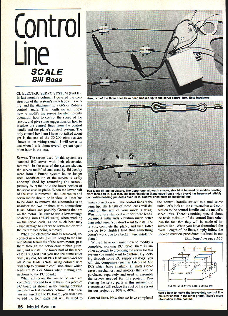
A piece of 1/16-in. OD copper tubing about 1/2 to 5/8 in. long can be crimped on the small line stub. Both ends of each line are made the same way. This small copper tubing acts as an electrical connection point and can be seen in the photos with an alligator clip attached, making connection to the switch control box.
Alternative connection method:
- Use Deans-type RC connectors. Solder small lengths of stranded wire into the 1/16-in. OD copper tubing and to the terminals of the Deans connector. Replace the alligator clips with the matching half of the Deans connector. It is advisable to use the Deans connector at the model end of the lines for a solid connection.
Control line insulation
The photos and sketch show a couple of suggestions for insulating the lines from the control handle and from the model's bellcrank system.
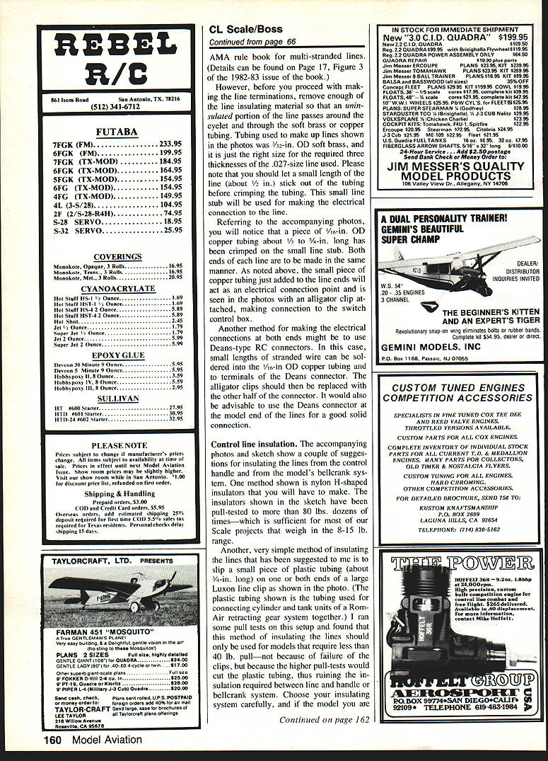
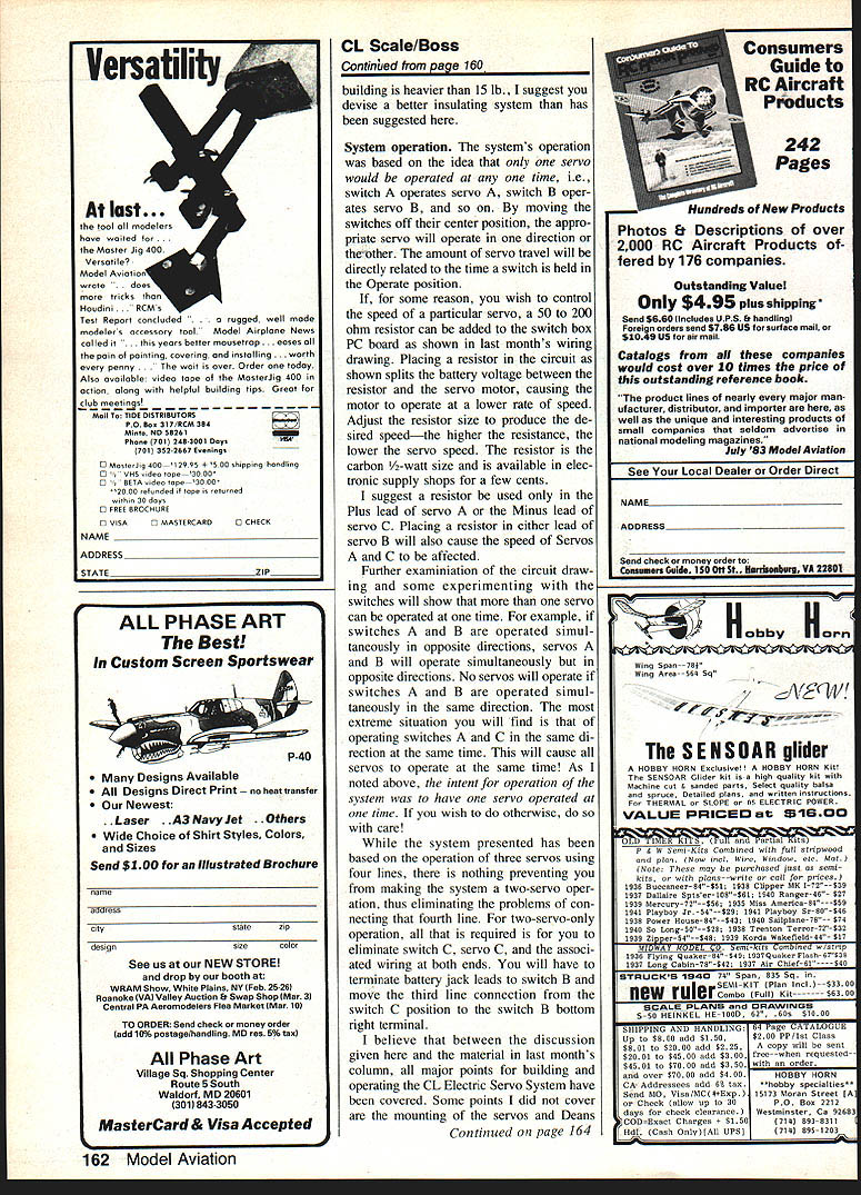
Method 1: Nylon H-shaped insulators
- Make H-shaped nylon insulators as shown in the sketch. These insulators have been pull-tested to more than 80 lbs. dozens of times, which is sufficient for most scale projects in the 8–15 lb. range.
Method 2: Plastic tubing on Luxon line clips
- Slip a small piece of plastic tubing (about 3/4 in. long) on one or both ends of a large Luxon line clip (the tubing shown is the tubing used for connecting cylinder and tank units of a Rom-Air retracting gear system).
- Pull tests indicate this method should only be used for models that require about a 40-lb. pull. Higher pull tests will cut the plastic tubing and ruin the required insulation between line and handle or bellcrank.
Choose your insulating system carefully. If the model you are building is heavier than 15 lb., I suggest you devise a better insulating system than those suggested here.
System operation
The system's operation is based on the idea that only one servo is operated at a time: switch A operates servo A, switch B operates servo B, and so on. By moving a switch off its center position, the appropriate servo will operate in one direction or the other. The amount of servo travel is directly related to the time a switch is held in the Operate position.
Controlling servo speed (resistor):
- If you wish to control the speed of a particular servo, a 50 to 200 ohm resistor can be added to the switch box PC board as shown in last month's wiring drawing.
- Placing a resistor in the circuit splits the battery voltage between the resistor and the servo motor, causing the motor to operate at a lower rate of speed. Adjust the resistor value to produce the desired speed—the higher the resistance, the slower the servo.
- Use a carbon 1/2-watt resistor; these are available in electronic supply shops for a few cents.
- I suggest using a resistor only in the Plus lead of servo A or the Minus lead of servo C. Placing a resistor in either lead of servo B will also affect the speed of servos A and C.
Multiple-switch behavior:
- More than one servo can be operated at once if desired:
- If switches A and B are operated simultaneously in opposite directions, servos A and B will operate simultaneously but in opposite directions.
- No servos will operate if switches A and B are operated simultaneously in the same direction.
- Operating switches A and C in the same direction at the same time will cause all servos to operate at once.
- The intent of the system is one servo at a time. If you choose to operate multiple servos simultaneously, do so with care.
Two-servo option:
- The system is based on three servos using four lines, but you can make a two-servo system and eliminate the fourth line.
- To do this, eliminate switch C, servo C, and the associated wiring at both ends.
- Terminate battery jack leads to switch B and move the third line connection from the switch C position to the switch B bottom-right terminal.
Final notes
I believe that between this discussion and last month's column, all major points for building and operating the CL Electric Servo System have been covered. I did not cover servo and Deans line-connector mounting in the model, or attachment of the fourth line to both the model and the control handle; I leave those details to your own ingenuity.
If you have comments or need additional information about this project, I would be glad to hear from you. Good luck.
Send CL Scale items to: Bill Boss 77-06 269th St. New Hyde Park, NY 11040
Transcribed from original scans by AI. Minor OCR errors may remain.

