
Control Line: Scale
Bill Boss
Rotary-switch operation
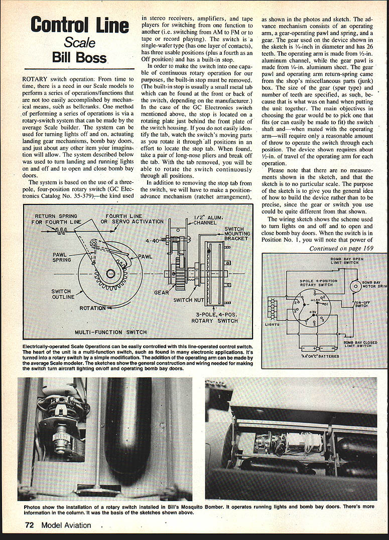
From time to time there is a need in our scale models to perform a series of operations or functions that are not easily accomplished by mechanical means such as bellcranks. One method of performing a series of operations is via a rotary-switch system that can be made by the average scale builder. The system can be used for turning lights on and off, actuating landing gear mechanisms, bomb bay doors, and just about any other item your imagination will allow. The system described below was used to turn landing and running lights on and off and to open and close bomb bay doors.
The system is based on the use of a three-pole, four-position rotary switch (GC Electronics Catalog No. 35-379)—the kind used in stereo receivers, amplifiers, and tape players for switching from one function to another (for example, switching from AM to FM or to tape). The switch is a single-wafer type (one layer of contacts), has three usable positions (plus a fourth as an Off position), and has a built-in stop.
Removing the built-in stop
To make the switch capable of continuous rotary operation for this application, the built-in stop must be removed. The stop is usually a small metal tab found at the front or back of the switch, depending on the manufacturer. In the GC Electronics switch mentioned above, the stop is located on a rotating plate just behind the front plate of the switch housing. If you do not immediately identify the tab, watch the switch's moving parts as you rotate it through all positions to locate the stop tab. When found, use long-nose pliers to break off the tab. With the tab removed, you will be able to rotate the switch continuously through all positions.
Position-advance mechanism (ratchet arrangement)
In addition to removing the stop tab, you must make a position-advance mechanism (ratchet arrangement). The advance mechanism consists of:
- an operating arm,
- a gear-operating pawl and spring,
- and a gear.
The gear used on the device shown in the sketch is 3/4 in. in diameter and has 26 teeth. The operating arm is made from 1/2 in. aluminum channel, while the gear pawl is made from 1/4 in. aluminum sheet. The gear pawl and operating-arm return spring came from the shop's miscellaneous parts box.
The gear is a spur type; the number of teeth is specified because that is what was on hand when the unit was put together. The main objectives in choosing the gear are to pick one that fits (or can easily be made to fit) the switch shaft and, when mated with the operating arm, will require a reasonable amount of throw to operate the switch through each position. The device shown requires about 1/2 in. of travel of the operating arm for each operation.
Please note that there are no measurements shown in the sketch and the sketch is not to scale. The purpose of the sketch is to give you the general idea of how to build the device rather than to be precise, since the gear or switch you use could be quite different from that shown.
The wiring sketch shows the scheme used to turn lights on and off and to open and close bomb bay doors.
Wiring and sequence of operations
Three volts is placed across the lights, and they are lit. When the switch is advanced to Position No. 2, the lights are turned off and 1.5 volts is placed across the bomb bay door motor drive, causing the bomb bay doors to open. When the doors are fully opened, the Open limit switch is actuated and the motor drive is turned off. At this point, the bomb bay Closed limit switch is still closed.
Advancing the rotary switch to Position No. 3 causes the bomb bay door-closed circuit to be actuated. When the doors are completely closed, the Closed limit switch opens once again, turning the circuit off. Advancing the rotary switch one more time puts the switch in the fourth (Off) position. The cycle can then be repeated.
The On-Off switch shown in the wiring sketch is not essential and can be eliminated if desired. It was used as a means of turning off the bomb bay motor-drive circuit to prevent operation during times when the model was on static display.
Please note that the voltages (battery supply) shown in the wiring sketch were for two batteries, grain-of-wheat bulbs, and a homemade geared motor drive for the bomb bay operation. If you decide to use this idea, you will have to adjust the battery supply voltage as required for the devices you will be operating.
CL Scale / Boss
(Continued from page 72)
Clarification — Electric servo operating system and control-line cable resistance
In my February and March 1984 columns I detailed an electric servo operating system for CL scale models and spoke about the use of two different types of insulated lines. One was the Nylon brand (Sullivan Products) .018 in. lines, and the other was .027 in. stainless-steel fishing leader.
The pictures and written material described the system operating with 4.8 volts at the handle. While the system operates satisfactorily using the Sullivan lines and 4.8 volts, it does not perform well when using the fishing leader.
When using the fishing leader for lines, 14–18 volts (two nine-volt transistor batteries in series will do fine) are required for good servo operation. A point I failed to cover in my initial article was the difference in resistance between the two types of lines and the need for increased voltage when using the fishing leader. The Sullivan lines have approximately 9 ohms resistance for commonly used lengths of control line (57–60 feet), while the fishing leader has over 30–35 ohms per line for the same length. The difference between the lines lies in the fact that the Sullivan lines have a copper core, which accounts for the much lower resistance.
I would like to thank Ernie Violett (College Park, MD) for bringing this problem to my attention and hope that the above information will help others who might be building the system and have run into the same operational problem.
Send articles on CL scale to Bill Boss, 77-06 269th St., New Hyde Park, NY 11040.
Transcribed from original scans by AI. Minor OCR errors may remain.

