
Control Line: Scale
Bill Boss
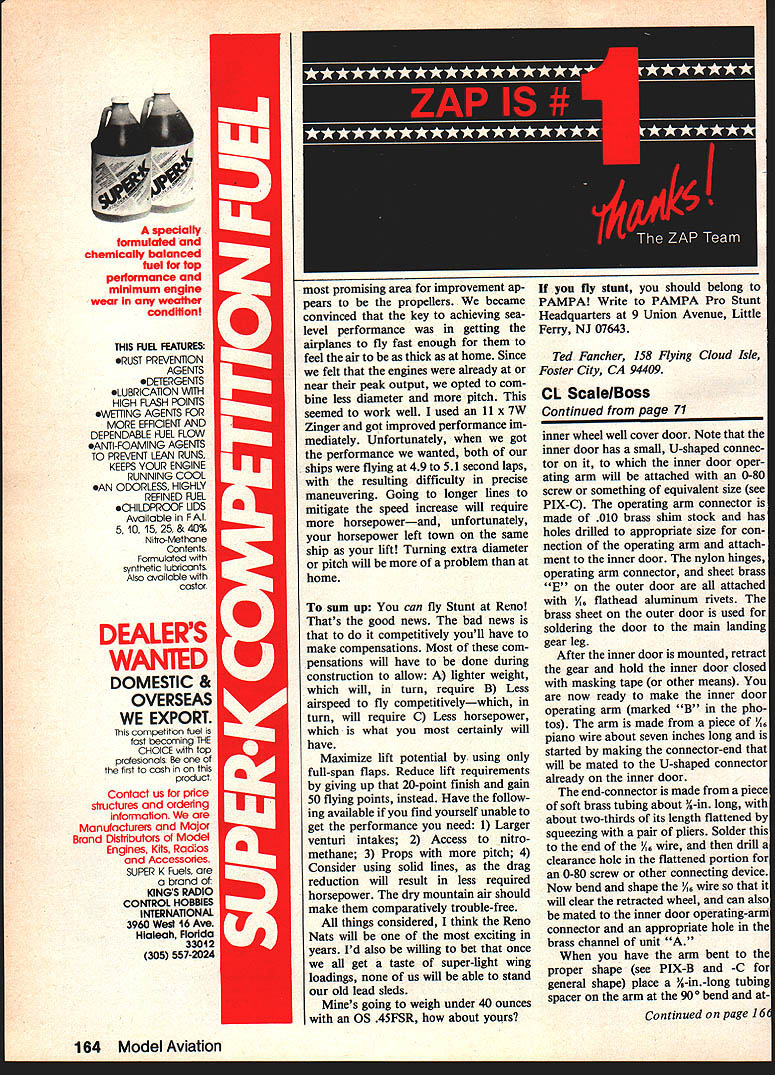
Inner-door operating mechanism for main landing gear
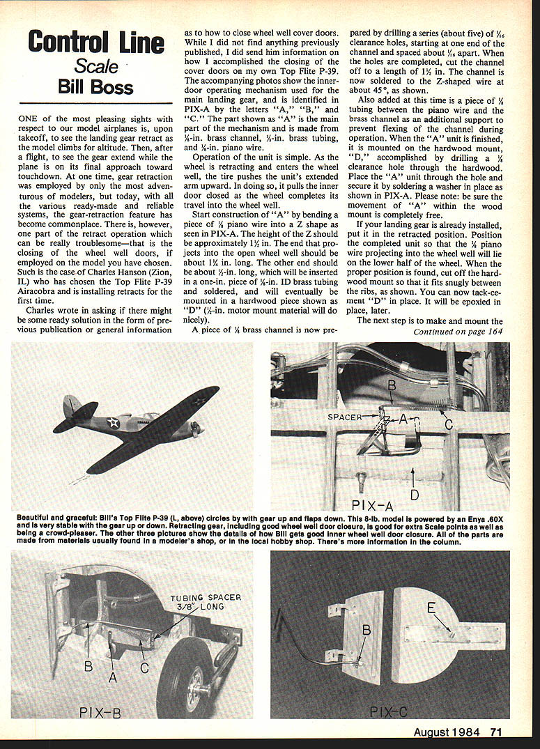
One of the most pleasing sights with respect to our model airplanes is, upon takeoff, to see the landing gear retract as the model climbs for altitude. Then, after a flight, to see the gear extend while the plane is on its final approach toward touchdown. At one time, gear retraction was employed by only the most adventurous modelers, but today, with the various ready-made and reliable systems, the gear-retraction feature has become commonplace. There is, however, one part of the retract operation which can be really troublesome—that is, the closing of the wheel-well doors, if employed on the model you have chosen.
Such is the case of Charles Hanson (Zion, IL), who chose the Top Flite P-39 Airacobra and is installing retracts for the first time. Charles wrote asking if there might be some ready solution in the form of previous publication or general information as to how to close wheel-well cover doors. While I did not find anything previously published, I sent him information on how I accomplished the closing of the cover doors on my own Top Flite P-39. The accompanying photos show the inner-door operating mechanism used for the main landing gear and are identified in PIX-A by the letters "A," "B" and "C."
The part shown as "A" is the main part of the mechanism and is made from 1/2-in. brass channel, 1/4-in. brass tubing (I.D.), and 1/16-in. piano wire.
Operation of the unit is simple. As the wheel retracts and enters the wheel well, the tire pushes the unit's extended arm upward. In doing so, it pulls the inner door closed as the wheel completes its travel into the wheel well.
Materials (for unit "A" and related parts)
- 1/16-in. piano wire
- 1/2-in. brass channel
- 1/4-in. I.D. brass tubing (short pieces)
- 1/8-in. tubing (support)
- 1/2-in. hardwood (motor mount material or similar) for mount "D"
- Washers for soldering/retaining
- 3/32-in. flathead aluminum rivets
- .010-in. brass shim stock (for connectors)
- Small screws or 0-80 screws (or equivalent)
- Small piece of brass tubing for arm connector
- 3/8-in. long tubing spacer
- Very light tension spring for door-opening (spring "C")
- Epoxy, solder, cement, masking tape
Construction of unit "A" (inner-door operating assembly)
- Bend a piece of 1/16-in. piano wire into a Z shape as shown in PIX-A. The height of the Z should be approximately 1-1/2 in. The end that projects into the open wheel well should be about 1-1/4 in. long. The other end should be about 1/2 in. long.
- Insert the short 1/16-in. wire end into a 1-in. piece of 1/4-in. I.D. brass tubing and solder it in place.
- Prepare a piece of 1/2-in. brass channel by drilling a series of about five 1/16-in. clearance holes, starting at one end and spaced about 1/8 in. apart. Cut the channel to a length of 1-1/2 in.
- Solder the brass channel to the Z-shaped wire at about 45° as shown in PIX-A.
- Add a short piece of 1/8-in. tubing between the piano wire and the brass channel for additional support to prevent flexing during operation.
- Mount the finished "A" unit on the hardwood mount "D" by drilling a 1/8-in. clearance hole through the hardwood, placing the "A" unit through the hole, and securing it by soldering a washer in place (see PIX-A). Ensure the movement of "A" within the wood mount is completely free.
Positioning and fitting
- If your landing gear is already installed, put it in the retracted position. Position the completed unit so the 1/16-in. piano wire projecting into the wheel well will lie on the lower half of the wheel. When the proper position is found, cut off the hardwood mount so it fits snugly between the ribs (see PIX-A).
- Tack-cement "D" in place for trial; it will be epoxied later.
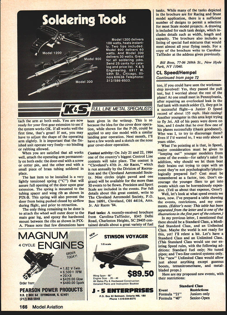
Outer door and inner-door connector
- The inner door has a small U-shaped connector on it to which the inner-door operating arm will be attached with an 0-80 screw (see PIX-C).
- The operating-arm connector is made from .010-in. brass shim stock with holes drilled to the appropriate size for the arm connection and attachment to the inner door.
- The nylon hinge, operating-arm connector, and sheet brass "E" on the outer door are attached with 3/32-in. flathead aluminum rivets. The brass sheet on the outer door provides a surface for soldering the door to the main landing gear leg.
Making the inner door operating arm (unit "B")
- Use a piece of 1/16-in. piano wire about 7 in. long.
- Make the connector end that mates to the U-shaped connector on the inner door: take a piece of soft brass tubing about 1/8 in. long, flatten about two-thirds of its length with pliers, solder it to the end of the 1/16-in. wire, and drill a clearance hole in the flattened portion for an 0-80 screw or similar connector.
- Bend and shape the 1/16-in. wire so it will clear the retracted wheel and can be mated to the inner-door operating-arm connector and to an appropriate hole in the brass channel of unit "A" (see PIX-B and PIX-C for general shape).
- Place a 3/8-in. long tubing spacer on the arm at the 90° bend and attach the arm at both ends temporarily for a test retraction/extension.
If the system works on the first trial, great. If not, adjust the shape of the operating arm slightly. It is important that the finished unit operate very freely—no binding or rubbing allowed.
When satisfied, attach the operating arm permanently at both ends: the door end with a screw or cotter pin, and the other end with a small piece of brass tubing soldered in place.
Spring assist (unit "C")
- Install a very lightly tensioned spring ("C") to assure full opening of the door upon gear extension. Mount the spring to the tubing spacer and wing rib as shown in PIX-B.
- This spring will also prevent the door from being pushed closed by airflow during flight and before retraction.
Final steps
- Attach the wheel-well outer door to the main gear leg.
- Epoxy the hardwood mount between the ribs as shown in PIX-A.
- Note: Few dimensions have been given because the cover-door operation idea, while shown for the P-39, can be applied to any size model with similar landing-gear operation.
Next month I'll have a few words and a sketch on the nose-gear cover-door operation.
Contest activity
On July 21 and 22, 1984 one of the country's biggest control-line contests will take place: Cleveland's 47th Jr. Air Races, run annually by the Division of Recreation and the Cleveland Aeromodel Society. Nine circles (eight paved and one grass) will be available for the more than 30 events to be flown. Precision and Sports Scale are included in the events. For full details about this contest, write to The Cleveland Aeromodel Society, P.O. Box 16091, Cleveland, OH 44116, Attn. Jr. Air Races '84.
Fuel tanks
A recently received brochure from Carolina-Taffinder, 8345 Deihl Road, Charleston Heights, SC 29405, contained details about a variety of fuel tanks. While many of the tanks depicted are for racing and stunt model application, there are sufficient designs to permit selection for most scale-model projects. A drawing is included for each tank design, showing width, length, and capacity. The brochure also includes a listing of special fuel mixtures that would meet almost all flying needs. For a copy of the brochure write to Carolina-Taffinder at the address given above.
Bill Boss 77-06 269th St. New Hyde Park, NY 11040
Transcribed from original scans by AI. Minor OCR errors may remain.

