
Control Line: Scale
Bill Boss
New Ways
One of the objectives of this column is to present ideas that will help the Control Line Scale modeler build and fly a better scale model. Over the past few months we have covered many building ideas, discussed scale documentation and rules changes, and described various operational functions.
In my February and March 1984 columns, I presented an electric servo system that allowed a number of functions to be performed through the use of electrified control lines and modified servos. That electric servo system, using three control lines, allowed the operation of two servos; the addition of a fourth line permitted the use of a third servo. While that system works, it is dependent on multiple lines which, when going beyond the three we are accustomed to using, becomes cumbersome.
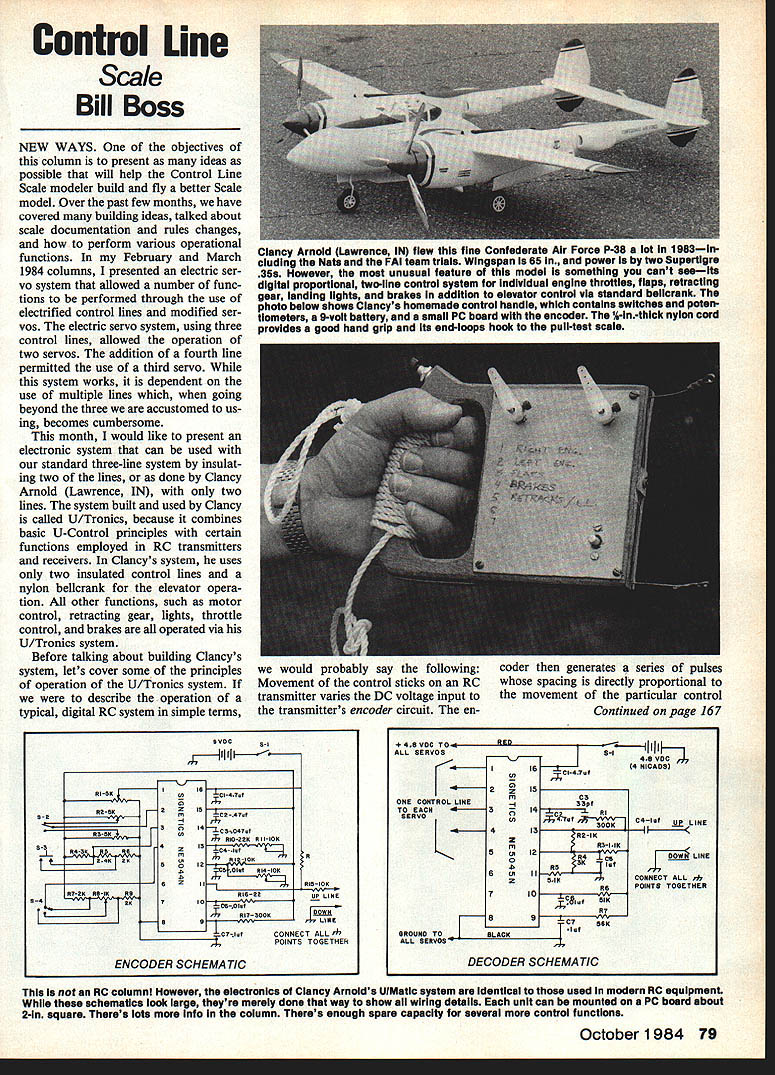
This month I present an electronic system that can be used with our standard three-line system by insulating two of the lines, or — as done by Clancy Arnold (Lawrence, IN) — with only two lines. The system built and used by Clancy is called U/Tronics, because it combines basic U-Control principles with certain functions employed in RC transmitters and receivers. In Clancy's system he uses only two insulated control lines and a nylon bellcrank for elevator operation. All other functions — motor control, retracting gear, lights, throttle control, and brakes — are operated via his U/Tronics system.
U/Tronics: Basic Principle
If we describe a typical digital RC system simply: movement of the control sticks on an RC transmitter varies the DC voltage input to the transmitter's encoder circuit. The encoder then generates a series of pulses whose spacing is directly proportional to the movement of the control stick. The pulses are sent to the transmitter's RF section where they modulate the broadcast signal. When received, the process is reversed: the receiver RF section passes the signal to the decoder, where the pulse stream is broken down and directed to particular servos for operation.
The U/Tronics system simply eliminates the transmitter and receiver RF sections, replacing them with a pair of insulated wires between the control handle and the airplane. No RF signal is used or transmitted — only a series of encoded electrical pulses are sent up the lines to the model.
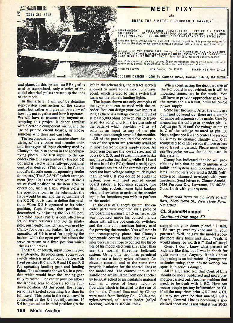
The encoder and decoder schematics may look large on paper, but are drawn that way to show wiring detail. Each unit can be mounted on a printed circuit (PC) board about 2 inches square, and each unit contains spare capacity for several more control functions.
This article gives an overview of how the system is put together and how it operates. It assumes anyone attempting the project is familiar with electronic component wiring and the use of printed circuit boards, or knows someone who can help.
Encoder Inputs (Examples Used by Clancy)
The accompanying schematics (not reproduced here) show the encoder and decoder wiring and four types of input circuitry that Clancy used in his P-38. The encoder has multiple input pins; the first four are shown here as representative examples:
- Fully proportional input (Pin 1)
- Represented by pot R-1 (5K).
- Used when fully-proportional control is desired (e.g., throttle control, cooler doors).
- Two-position SPDT input (Input 2)
- Uses switch S-2 (SPDT) and pots R-2 and R-3 (5K each).
- When S-2 is in the "up" position, flaps are up and R-2 defines that position. When S-2 is in the other position, flaps are down and R-3 defines that position.
- Push-button brake input (Pin 3)
- Controlled by fixed resistors and S-3 (single-pole, push-button switch).
- S-3 applies the brakes; when open the servo returns to a fixed position to release the brakes.
- Three-position rotary input for retracts and lights (S-4)
- S-4 is a single-pole, three-position rotary switch used with fixed resistors R-7 and R-9 and pot R-8 (1K).
- One position: landing gear fully retracted.
- Center position: landing gear full down but retract servo travels less than maximum; R-1 pot adjustment controls the point in travel.
- Third position: retract servo allowed full travel to trip a switch that turns on landing lights.
These inputs are examples only. You can design other inputs provided there is a voltage-divider circuit of at least 5,000 ohms between Pin 15 (regulated +5 V) and Pin 8 (battery return) which supplies about +2 to +3 volts as an input to any of encoder pins 1 through 7.
Parts and Construction
- Fixed resistors: 1/4-watt size.
- Pots: miniature size with adjusting shafts for R-1, R-2, R-3, and R-8. R-11 and R-14 may be PC (printed circuit) type.
- Capacitors: ceramic type, voltage rating need not exceed about 12 V.
- PC board: about a four-inch square recommended for parts layout; each unit can fit on about a 2-inch square board.
- Two 16-pin chip sockets, light hookup wire, and switches for encoder inputs.
- When constructing the decoder, board size is not critical; it must simply fit in the model with room for servos and battery.
All parts are generally available from most electronic parts suppliers.
Clancy's Implementation Details
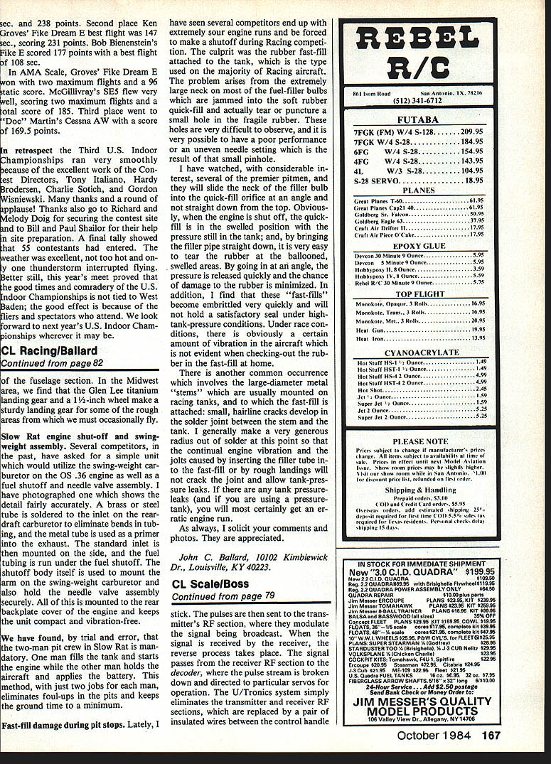
- Clancy mounted the encoder parts on a PC board measuring about 1 x 1.5 inches inside his control handle along with pot controls, switches, and a single nine-volt transistor battery to power the encoder.
- He used only two control lines because he controlled throttles electronically rather than using the normal three-line bellcrank system. Using two lines permitted a heavy nylon bellcrank for elevator control and allowed insulation of the control lines at the model end.
- Control lines used by Clancy were Berkley Co. 120-lb.-test nylon-covered saltwater leader (called Steelon), .027-inch thick.
- Control lines at the handle end are insulated from one another by being attached to an insulating material (heavy nylon or fiberglass) fastened to the rear of the handle.
Decoder and Power Requirements
- The decoder is mounted somewhere in the model. Provide appropriate space for servos.
- Power supply for decoder/servos: 4.8 V, 550 mAh Ni-Cd battery pack.
- Note: only positive pulse servos should be used with this system.
Final Adjustments and Setup
After building and powering the units, perform these adjustments:
- Measure the voltage at encoder Pin 13.
- Adjust pot R-14 until the voltage at Pin 12 is one-third of the voltage measured at Pin 13.
- Adjust pot R-11 to center the servos.
- If more or less servo travel is desired, change R-14 slightly and readjust R-11 to re-center.
Help and Contact Information
Clancy Arnold has offered to help anyone building the system who encounters problems. He requests that you send a self-addressed, stamped envelope (SASE) with your questions to:
Clancy Arnold 5434 Purpura Dr. Lawrence, IN 46236
Please send items on CL Scale to: Bill Boss 77-06 269th St. New Hyde Park, NY 11040
Transcribed from original scans by AI. Minor OCR errors may remain.

