
Control Line: Scale
Bill Boss
Introduction
Back to basics on our three-line control system. From time to time we have to return to square one and cover very basic Control Line (CL) flying topics. Experienced builders and fliers can forget there are beginners or those trying something for the first time. Such was the case with James Griffin (Philadelphia, PA), who was just getting into Scale modeling and using the three-line control system.
James' problem was that his three-line system would not operate through the full range of control without leaving slack in the lines at the high- and low-speed extremes. After reading his letter, it appeared his system simply did not have all three lines of equal length, and the model's control (third) lead did not have the proper length to create a balanced system. The discussion below returns to the basics of the three-line system and points out common problem areas.
Three-Line System Basics
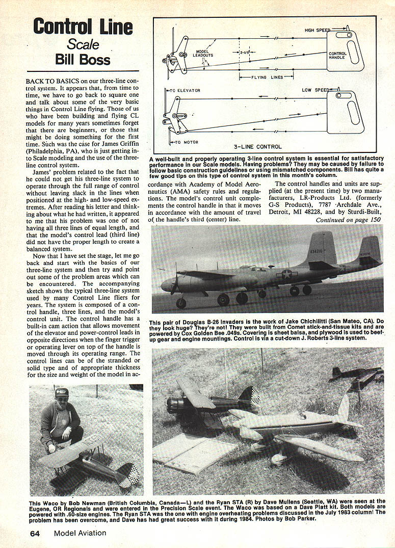
The typical three-line system is composed of:
- a control handle,
- three control lines (two elevator lines and one control/power line), and
- the model's control unit.
The control handle has a built-in cam action that moves the elevator and the power-control lead in opposite directions when the finger trigger or operating lever on top of the handle is moved through its range. Control lines may be stranded or solid and must be of appropriate thickness for the model's size and weight in accordance with Academy of Model Aeronautics (AMA) safety rules and regulations. The model's control unit mirrors the movement commanded by the handle's third (center) line and provides control of throttle, bomb release, retracts, etc.
Manufacturers and Compatibility
Control handles and units are currently supplied by two manufacturers:
- LR-Products Ltd. (formerly G-S Products), 7787 Archdale Ave., Detroit, MI 48228
- Sturdi-Built (J. Roberts Flight Control system), 4203 S. Cloverdale Rd., Boise, ID 83705
Both systems work equally well if assembled correctly using matched parts supplied by each manufacturer. They operate on the same principle: movement of the handle moves the model's control unit an equal amount. However, there is a difference in the available travel of the control lead (third line):
- J. Roberts Flight System: approximately 1½ in. travel
- LR-Products units: approximately 1¾ in. travel
If you mix components from different manufacturers, account for this travel difference (about ¼ in.) to avoid improper operation. For example:
- J. Roberts handle + LR control unit: you will not obtain the full travel available in the LR unit.
- LR handle + Sturdi-Built control unit: the handle may have more travel than the model unit, potentially producing slack elevator lines if the handle is forced to maximum travel, which can create an unsafe condition.
Setup and Adjustment
Key setup rules:
- All three lines between the handle and the model must be of equal length.
- The model's control (third-line) leadout must be 2½ in. longer than the elevator leadouts. Note: the 2½ in. measurement must be made with the elevator leadouts pulled tight (the system's high-speed position) and held even with each other.
If the system is built this way, it should be balanced and maintain equal tension on all three lines throughout the control range.
Mounting Options
Model control units come in two forms:
- Upright: most often used for profile and full-bodied models and most Sport Scale models where cockpit detail is limited.
- Suspended (lower-mounted): useful for Precision Scale models when you want to hide the control unit and provide a full cockpit floor with maximum detail. Mount the unit in the lower half of the wing thickness in this case.
Installation and Smooth Operation
During installation, ensure:
- All components work smoothly with no binding, especially where leadouts pass through ribs, wing tips, or guides.
- Leadouts are routed and supported to prevent friction or rubbing.
A little extra care during building produces a smooth-working, well-balanced system.
Terminology: Overhang
"Overhang" is the distance from the wrist hinge-point to the outermost point on the control handle where the leadout wires emerge from the handle structure. For discussion purposes, assume the distance from the wrist hinge-point to the front of the handle grip is 3-1/2 in.
Measurements, Assumptions, and Limits
For the analyses and tables referenced in this and related columns:
- Deflection, angles, and forces are derived from measurements of reasonably accurate full-scale drawings rather than purely mathematical derivations.
- All force measurements assume a total line tension (pull) of 30 lb., divided equally between the Up and Down lines (i.e., 15 lb. per line).
A friction-free control system will share the load equally between the elevator lines throughout control deflections—up to the point of maximum control deflection. If you "hang the airplane" on a single line (a symptom of a poorly trimmed airplane), the load-sharing assumption no longer holds.
The radius of rotation (handle deflection) for control inputs is measured from the wrist hinge-point to the line-attach points (as described in the overhang discussion). Greater line spacing (overhang) gives a larger radius of rotation and therefore greater sensitivity for a given angle of handle rotation.
For simplicity, handle rotations of 0°, 15°, 30°, and 45° are commonly used in comparisons. Pilot arm or body inputs are not considered here; they would apply equally to any handle design and are reasonably ignored for these basic mechanical discussions. The handle's function is taken to be movement of the leadouts at the wing tip; a linear measurement of their movement reflects handle inputs.
Response Rate and Relative Sensitivity
Relative sensitivity (response rate) depends on line spacing. Example analyses plot the Up and Down line positions at handle rotations of 0°, 15°, 30°, and 45° for leadout spacings of 2 in., 4 in., and 5 in. The line-attach-point differential between Up and Down lines gives control line displacement from neutral at the handle and, therefore, at the wing tip. Larger spacing produces larger displacement for a given rotation angle, making the handle more sensitive.
One item to remember: the maximum line displacement available from a handle is equal to the line spacing. No matter what you do with your hand, the maximum displacement cannot exceed the line spacing.
Practical Notes
- Take care when mixing components from different manufacturers; plan operational functions to accommodate travel differences and avoid unsafe conditions.
- Pay attention to mounting type (upright vs. suspended) depending on model type and cockpit detail requirements.
- Ensure friction-free routing and adequate spacing to maintain equal line tension through the control range.
Send items on CL Scale to: Bill Boss 77-06 269th St. New Hyde Park, NY 11040
Transcribed from original scans by AI. Minor OCR errors may remain.

