
CONTROL LINE SPEED
Glenn Lee 819 Mandrake Drive, Batavia, IL 60510
Introduction
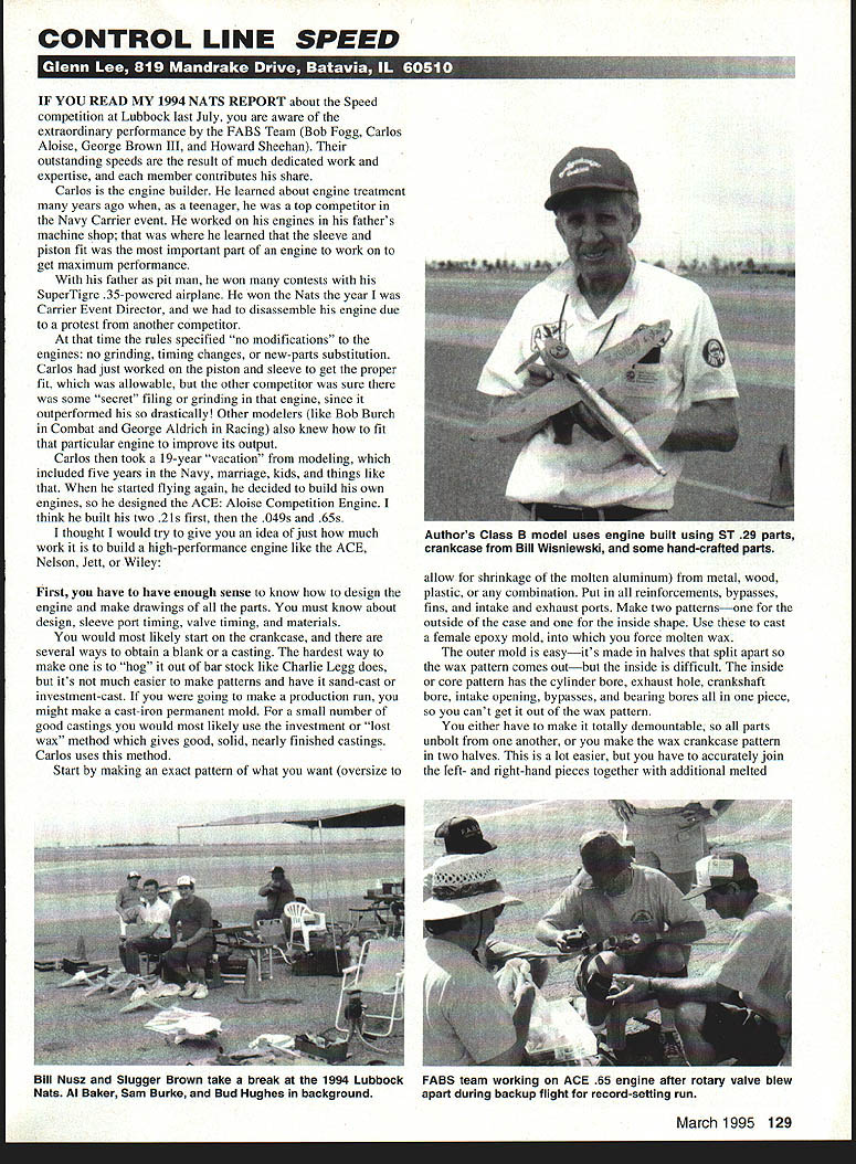
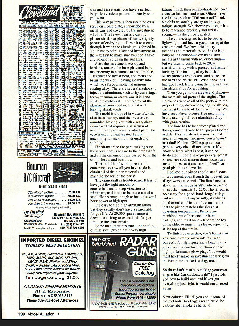
If you read my 1994 NATS report about the Speed competition at Lubbock last July, you are aware of the extraordinary performance by the FABS Team (Bob Fogg, Carlos Aloise, George Brown III, and Howard Sheehan). Their outstanding speeds are the result of much dedicated work and expertise, and each member contributes his share.
Carlos Aloise — the engine builder
Carlos is the engine builder. He learned about engine treatment many years ago when, as a teenager, he was a top competitor in the Navy Carrier event. He worked on his engines in his father's machine shop; that was where he learned that the sleeve and piston fit was the most important part of an engine to work on to get maximum performance.
With his father as pit man, he won many contests with his SuperTigre .35–powered airplane. He won the NATS the year I was Carrier Event Director, and we had to disassemble his engine due to a protest from another competitor.
At that time the rules specified "no modifications" to the engines: no grinding, timing changes, or new-parts substitution. Carlos had just worked on the piston and sleeve to get the proper fit, which was allowable, but the other competitor was sure there was some "secret" filing or grinding in that engine, since it outperformed his so drastically! Other modelers (like Bob Burch in Combat and George Aldrich in Racing) also knew how to fit that particular engine to improve its output.
Carlos then took a 19-year "vacation" from modeling, which included five years in the Navy, marriage, kids, and things like that. When he started flying again, he decided to build his own engines, so he designed the ACE: Aloise Competition Engine. I think he built his two .21s first, then the .049s and .65s.
I thought I would try to give you an idea of just how much work it is to build a high-performance engine like the ACE, Nelson, Jett, or Wiley.
Design and planning
First, you have to have enough sense to know how to design the engine and make drawings of all the parts. You must know about design, sleeve-port timing, valve timing, and materials.
You would most likely start on the crankcase, and there are several ways to obtain a blank or a casting. The hardest way to make one is to "hog" it out of bar stock like Charlie Legg does, but it's not much easier to make patterns and have it sand-cast or investment-cast. If you were going to make a production run, you might make a cast-iron permanent mold. For a small number of good castings you would most likely use the investment or "lost wax" method, which gives good, solid, nearly finished castings. Carlos uses this method.
Making the pattern and investment mold
Start by making an exact pattern of what you want (oversize to allow for shrinkage of the molten aluminum) from metal, wood, plastic, or any combination. Put in all reinforcements, bypasses, fins, and intake and exhaust ports. Make two patterns—one for the outside of the case and one for the inside shape. These two cast a female epoxy mold, into which you force molten wax.
The outer mold is easy—it's made in halves that split apart so the wax pattern comes out—but the inside is difficult. The inside or core pattern has the cylinder bore, exhaust hole, crankshaft bore, intake opening, bypasses, and bearing bores all in one piece, so you can't get it out of the wax pattern.
You either have to make it totally demountable, so all parts unbolt from one another, or you make the wax crankcase pattern in two halves. This is a lot easier, but you have to accurately join the left- and right-hand pieces together with additional melted wax and trim it until you have a perfect (slightly oversize) pattern of exactly what you want.
This wax pattern is then mounted on a sprue on a base plate, surrounded by a metal can, and covered by the investment solution. The investment is a casting plaster similar to plaster of Paris, slightly porous after drying to allow air to escape through it when the aluminum is forced into it. You have to paint a layer of investment on the wax first to make sure you don't have any holes or voids on the surfaces.
After the investment sets up and hardens, remove the base plate and bake the assembly in a furnace at about 600°F. This dries the investment and melts and burns the wax out, leaving a cavity in which you force a molten aluminum casting alloy. There are several methods to inject the aluminum, such as by centrifugal force, vacuum, or steam, and it is done while the mold is still hot to prevent the aluminum from cooling too fast and leaving shrink voids.
The mold is dropped in water after the aluminum sets up, and the investment crumbles, leaving you with a nice, clean crankcase that requires a minimum of machining to produce a finished part. The case is usually heat-treated before machining for maximum strength and stability.
Finish-machine the part, making sure the sleeve bore is square to the crankshaft, and all the dimensions are correct to fit the shaft, sleeve, and bearings.
That little bit of work gave you a crankcase, so now all you have to do is obtain all of the other materials and machine the rest of the parts!
Crankshaft
The crankshaft is troublesome. It has to have just the right amount of counterbalance to keep vibration to a minimum, and it has to be made out of a steel alloy strong enough to handle several horsepower at high rpm.
It's easy to find high-strength alloys, but they usually don't have a reasonable fatigue life. At 20,000 rpm or more it doesn't take long to exceed this fatigue limit, so the shaft breaks.
Some manufacturers made the shaft out of mild steel (which has a very high fatigue limit), then surface-hardened some areas for bearings and wear. Others have used alloys such as "fatigue proof" steel, which is reasonably strong and has good fatigue strength. Whichever you use, it has to be machined precisely and finish-ground—maybe chrome plated.
Connecting rod
The connecting rod has to be strong, lightweight, and have a good bearing at the crankpin end. We have tried many methods and materials to obtain the best, long-lasting conrod—even using such metals as titanium with roller bearings—but we usually come back to 2024 aluminum alloy with a pressed-in bronze bushing. The bushing alloy is critical. Many bronzes are too soft, and some are too hard and brittle. Bill Wisniewski has had good luck lately using the high-silicon aluminum alloy for a bushing.
Sleeve and piston
Then you get to the sleeve and piston—the most critical parts of the engine. The sleeve has to have all of the ports with the proper timing, dimensions, angles, and shapes, and must be made of the correct alloy. We have used naval bronze, free-machining brass, and high-silicon aluminum alloy with good results.
The bore has to be chrome plated and then ground or honed to the proper tapered profile. This profile is the most critical area in an engine, and gives you a "goer" or a dud! Modern CNC equipment can grind to very close dimensions, so if you know or learn what is best, it can be duplicated. I don't have proper equipment to measure such micron dimensions, so I have to guess at it and rely on "feel" for good piston-to-sleeve fits.
I believe our pistons could stand some improvement, even though the high-silicon alloys work quite well. The Russians use alloys with as much as 28% silicon, while most others contain 19–22%. The silicon is necessary for a good, hard, long-lasting surface, but most importantly, it reduces the thermal coefficient of expansion so the piston matches the sleeve at operating temperatures. Pistons are machined out of bar stock or from castings and must have a taper at the top of the sides to match the sleeve, especially at the top of the stroke.
Finishing touches
To finish your engine, don't forget that you need a rotary valve intake (timed correctly for high rpm) and a head with a good-running combustion chamber and high-performance glow plug. You would most likely make an investment casting for the backplate-intake housing, too.
So there isn't much to making your own engine like Carlos does, right? I just told you how to build one, and if you got everything just right, it would run as good as his!
Next column I'll tell you about some of the methods Bob Fogg uses to build the carbon-fiber airplane shells.
Transcribed from original scans by AI. Minor OCR errors may remain.

