
Control Line: Speed
Glenn Lee, 819 Mandrake Drive, Batavia IL 60510
Turbojets
Most of you have probably seen write-ups, advertisements, and maybe even demonstrations of the small turbojet engines that modelers have been trying in RC scale airplanes.
From what I have read, the early engines required a rather complicated starting system and had other problems such as fuel, fuel tanks, and safety concerns. It took a crew of several persons to start them, just like full-scale jet engines.
Newer versions have been improved and simplified until they can be started and operated by one person. I saw a demonstration flight at the Nats, and it was impressive to say the least! The sound was just like a full-scale jet, and thrust and speed were outstanding. Some of us Speed fliers wondered how it would be to fly one Control Line, but we realized that it might be a little too large and too powerful.
There's a new turbojet engine available that is only 4.3 inches in diameter and weighs just 26.5 ounces! It puts out 7.5 lb. of thrust at a rotor speed of 100,000 rpm—enough to fly Control Line-size models. Can we fly Turbojet Speed? It might be a while for that, but we can seriously think of using such an engine in CL scale now.
The tiny turbojet was built by a company called Golden West Models and was based on Kurt Schreckling's design for model aircraft, which was put into production by Schneider-Sanchez of Austria. Recently, Engineering News magazine had a short write-up on several of these engines that put out 7.5 to 100 lb. of thrust and range from 26.5 oz. to 16 lb.
Golden West Models' FD 3/67 LS engine, the small one, is made from exotic metals such as Inconel, titanium, and stainless steel, and has punched blades with curvature instead of machined-and-welded turbines. A patented electronic control regulates fuel flow, depending on input from an exhaust gas temperature sensor, engine tachometer, and throttle setting.
A second patent covers a fuel vaporization system that carries the kerosene–Coleman gas through 3/16-inch-diameter Inconel tubing in the combustion chamber. The engine cost was reported at $2,995. I can just see the future now—jet carrier, jet aerobatics, jet racing, jet combat! Talk about Top Gun!
Cold Cash Speed Bash
Last September I competed at the 50th Anniversary Speed Contest hosted by the Dayton Buzzin' Buzzards. Harry Roe, an avid Speed flier who has been around forever, found one of the flyers for the very first Dayton contest held in 1947. Control Line modeling was still new then, so rules were still in the formative stage.
Speed consisted of five classes at first, starting with engines at .10 maximum displacement and progressing to .20, .30, .40, .50, and .60. Soon, they settled down to Class A for .19s; Class B for .29s; Class C for .49s; and Class D for .60s. Then someone found out that most .60-size engines were a little over the .60 size limit. So the Class D size was raised to .65—we've stuck with it ever since.
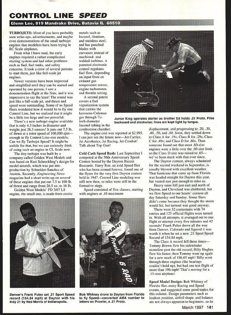
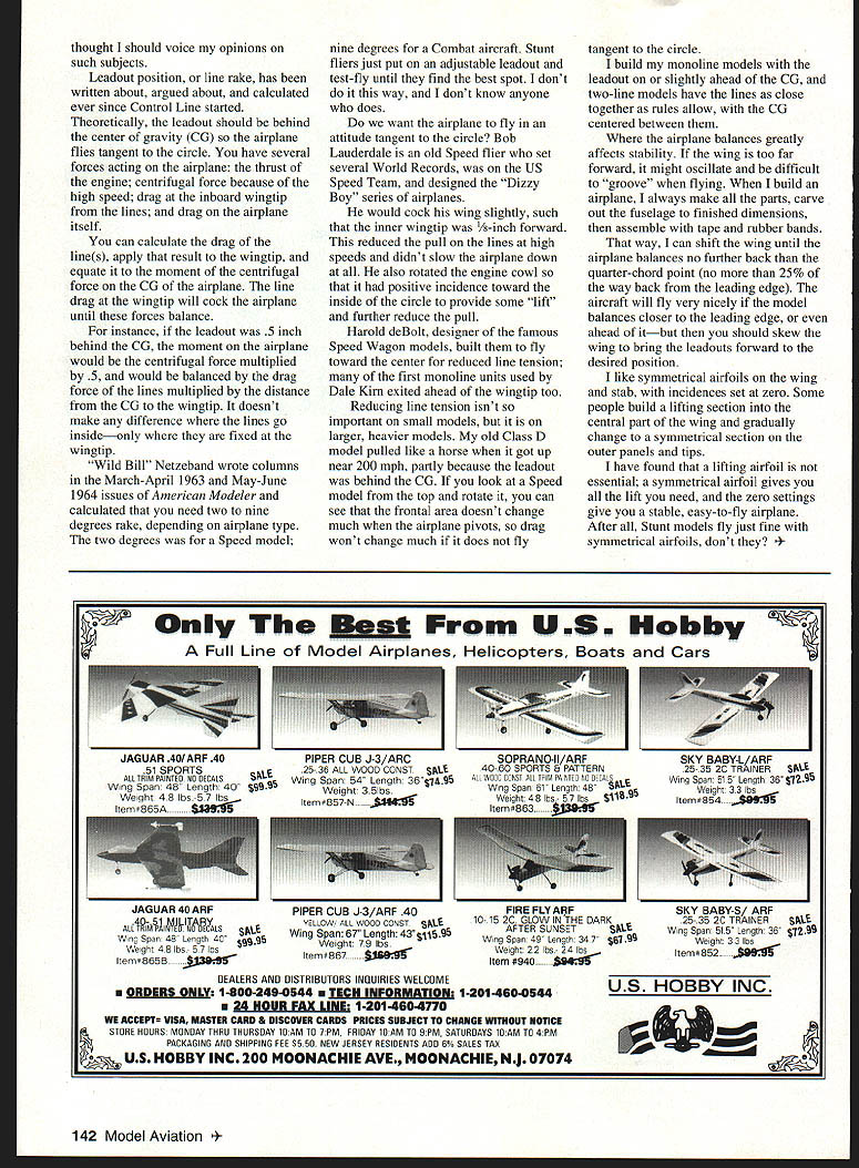
The Dayton contest, always scheduled for the second weekend in September, is usually blessed with excellent weather. That hurricane that came up from Florida was headed straight for Dayton this year, but veered east just enough to miss us. Heavy rains fell just east and north of Dayton, and Cleveland was clobbered, but we flew Speed to our hearts' content all day Saturday and Sunday. Some fliers didn't come because they thought the storm would hit, but turnout was good anyway. There were 32 contestants with 74 entries and 125 official flights were turned in. With all attempts, it averaged out to one flight or attempt every five minutes and 42 seconds! Frank Puleo drove all the way from Denver, Colorado and figured it was worth it when he set a new .21 Sport Speed record of 154.84 mph.
The Class A record fell three times—Tommy Brown flew his sidewinder monoline past the old record; Billy Hughes flew his faster; then Tommy went up again for a new mark of 186.65 mph! Billy went through three engines (the bearings couldn't hold up), but had one test flight of more than 196 mph! That's moving for a .15-size airplane!
Speed Model Design
Bob Whitney of Florida flies many Racing and Speed events and suggested some good topics for this column. Design parameters such as leadout position, airfoil shape, and balance are not always apparent to beginners, so the next column will cover those subjects. I thought I should voice my opinions on such subjects.
Leadout position, or line rake, has been written about, argued about, and calculated ever since Control Line started.
Theoretically, the leadout should be behind the center of gravity (CG) so the airplane flies tangent to the circle. You have several forces acting on the airplane:
- the thrust of the engine
- centrifugal force because of the high speed
- drag at the inboard wingtip from the lines
- drag on the airplane itself
You can calculate the drag of the line(s), apply that result to the wingtip, and equate it to the moment of the centrifugal force on the CG of the airplane. The line drag at the wingtip will cock the airplane until these forces balance.
For instance, if the leadout was 0.5 inch behind the CG, the moment on the airplane would be the centrifugal force multiplied by 0.5, and would be balanced by the drag force of the lines multiplied by the distance from the CG to the wingtip. It doesn't make any difference where the lines go inside—only where they are fixed at the wingtip.
"Wild Bill" Netzeband wrote columns in the March–April 1963 and May–June 1964 issues of American Modeler and calculated that you need two to nine degrees rake, depending on airplane type. The two degrees was for a Speed model; nine degrees for a Combat aircraft. Stunt fliers just put on an adjustable leadout and test-fly until they find the best spot. I don't do it this way, and I don't know anyone who does.
Do we want the airplane to fly in an attitude tangent to the circle? Bob Lauderdale is an old Speed flier who set several world records, was on the US Speed Team, and designed the "Dizzy Boy" series of airplanes. He would cock his wing slightly, such that the inner wingtip was 1/2 inch lower. This reduced the pull on the lines at high speeds and didn't slow the airplane down at all. He also rotated the engine cowl so that it had positive incidence toward the inside of the circle to provide some "lift" and further reduce the pull.
Harold deBolt, designer of the famous Speed Wagon models, built them to fly toward the center for reduced line tension; many of the first monoline units used by Dale Kimet exited ahead of the wingtip too.
Reducing line tension isn't so important on small models, but it is on larger, heavier models. My old Class D model pulled like a horse when it got up near 200 mph, partly because the leadout was behind the CG. If you look at a Speed model from the top and rotate it, you can see that the frontal area doesn't change much when the airplane pivots, so drag won't change much if it does not fly tangent to the circle.
I build my monoline models with the leadout on or slightly ahead of the CG, and two-line models have the lines as close together as rules allow, with the CG centered between them.
Where the airplane balances greatly affects stability. If the wing is too far forward, it might oscillate and be difficult to "groove" when flying. When I build an airplane, I always make all the parts, carve out the fuselage to finished dimensions, then assemble with tape and rubber bands.
- Make all the parts.
- Carve the fuselage to finished dimensions.
- Assemble temporarily with tape and rubber bands.
- Shift the wing until the airplane balances no further back than the quarter-chord point (no more than 25% of the way back from the leading edge).
That way, I can shift the wing until the airplane balances no further back than the quarter-chord point. The aircraft will fly very nicely if the model balances closer to the leading edge, or even ahead of it—but then you should skew the wing to bring the leadouts forward to the desired position.
I like symmetrical airfoils on the wing and stab, with incidences set at zero. Some people build a lifting section into the center part of the wing and gradually change to a symmetrical section on the outer panels and tips.
I have found that a lifting airfoil is not essential; a symmetrical airfoil gives you all the lift you need, and the zero settings give you a stable, easy-to-fly airplane. After all, stunt models fly just fine with symmetrical airfoils, don't they?
Transcribed from original scans by AI. Minor OCR errors may remain.

