
Control Line: Speed
Gene Hempel
Before starting into this month's column, let me mention that I was delighted to hear from some inquisitive readers. I was beginning to wonder if anyone ever read this column. It is difficult to write about something if you have no feedback from the readers. I appeal to you—keep those cards and letters coming—even if it's just to say, "hi". If there is something you would like to share, send it on, especially if it pertains to engine work. It may seem unimportant to you, but there are many modelers who are just starting and are interested in all sorts of "good poop." There are many boaters that read this column for engine information. Hope you boaters write about your engine problems and solutions!
I finally "blackmailed" Nick Sher into writing an article on 1/2 A speed. Nick has done an outstanding job making the Cox T.D. .049 perform extremely well. He has agreed to share all his secrets in this month's column. His copy follows:
Nick Sher — 1/2A Speed Techniques
Gene Hempel requested that I write an article about 1/2 A speed, specifically engine modifications. The information supplied is an accumulation of knowledge and experience from such engine experts as Frank Garzon, Dub Jett, John Shannon, Mike Langlois, and the like. It has been fun to implement these ideas, plus a few of my own.
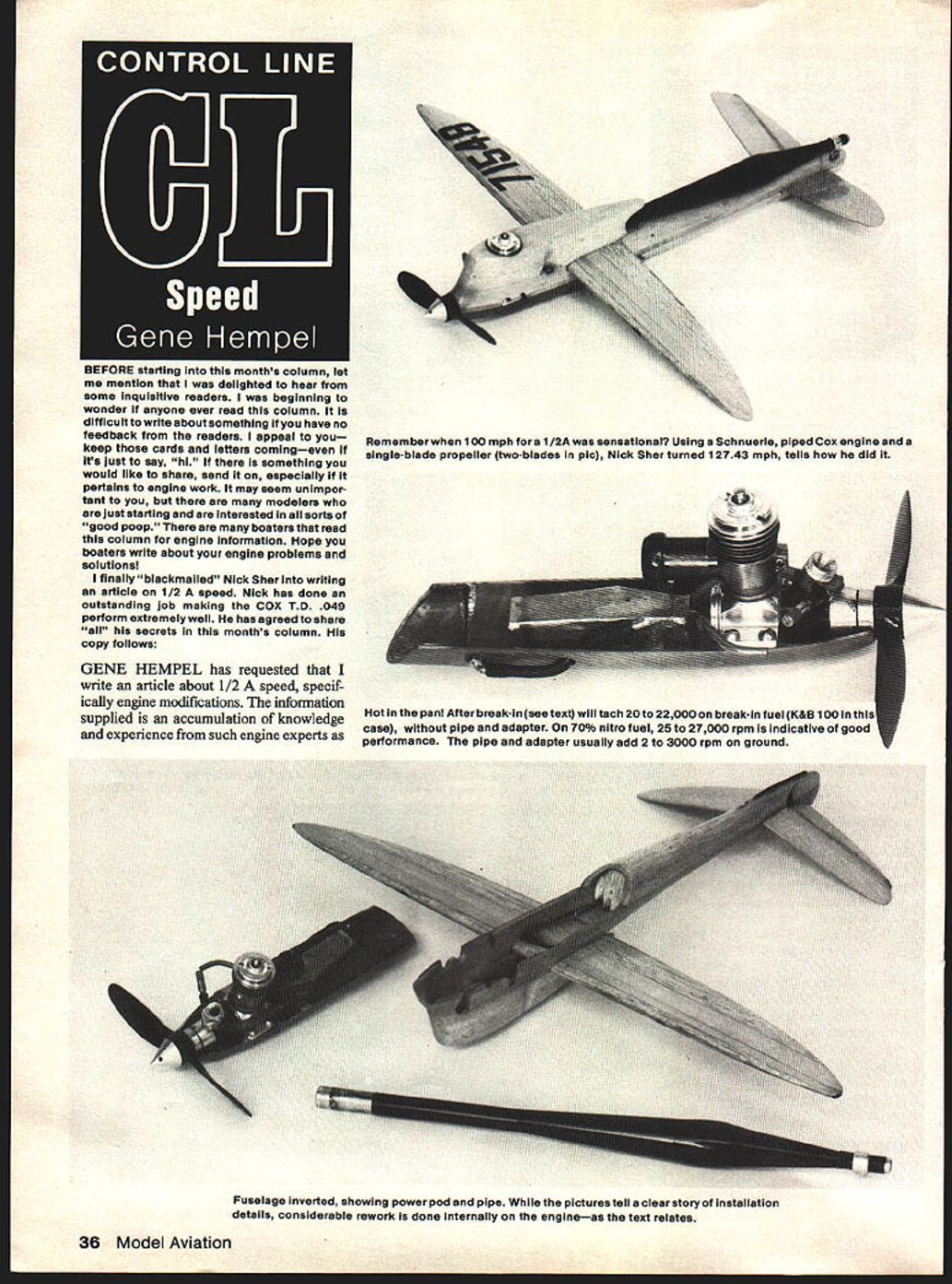
At my last speed meet of the season in Flushing, New York, using a Schnuerle-piped Cox and a single-bladed prop (my first) and Frank Garzon on the needle, I turned a slightly lean 7.06 sec. (127.43 mph). The top shell of the ship was rubbing against the prop driver, so I did not fly it again. Here are some of the techniques used to achieve that speed.
All of the numbers in the article were measured directly from the engine used in that Flushing meet. I have gone to great lengths to make these measurements accurately. I have too much respect for the hobby and the people that may read this to do otherwise.
Tips on 1/2A Speed
- Crankcase Selection
- Place the case in a Cox speed pan and check for flatness of mounting lugs with the pan versus the centerline of the shaft bearing to the centerline of the pan.
- If inspection tools are available, check for shaft-to-cylinder centerline alignment and mounting lug flatness and parallelism to the shaft bearing centerline.
- Shaft Selection
- Locate or obtain several shafts that have the thick counterweight web (latest series).
- Using a depth micrometer, select a shaft that has the longest stroke, i.e., measure stroke of piston in a partially assembled engine changing only the shaft.
- Remember, 1/2 A displacement can go to 0.0504 cu. in., according to the AMA rule book.
- After measuring the stroke, check and be sure that the crank rod journal is in the center when looking down into the cylinder barrel from the top. This is very important.
- Before removing the shaft from the case, check the front-to-rear alignment of the shaft intake port in relation to the case intake opening. You may have to remove some metal either from the case or the shaft for proper alignment.
- T.D.C. Alignment
- Temporarily assemble the shaft, case, piston and blank cylinder. Tighten the cylinder and measure piston depth versus plug step depth in the cylinder with the piston at top dead center (T.D.C.) using a depth micrometer.
- The piston is generally .005 to .007 in. above the step.
- Select a metal gasket washer (I use stainless steel) with a thickness that will cause alignment of the piston top with the glow plug step (at T.D.C.) when the washer is placed under the cylinder base mounting surface.
- Make certain that the washer is in place during the cylinder timing measurements.
- Engine Timing
a) Shaft
- Grind open the transfer hole in the shaft to 0.200 in. diameter and time the port to open at 35 degrees ABDC and close at 65 degrees ATDC.
- I then have the shaft flash-chromed, polished and fitted to the case by honing the case bearing hole.
- The timing modification of the crankshaft is accomplished by the following method:
1) Paint some layout blue around the port opening of the shaft. 2) Insert the shaft into the case and mount a degree wheel to the shaft of the assembled engine. 3) Scribe the opening and closure lines on the shaft using a sharp needle. 4) After removing the shaft from the case, remove material from the shaft with a Dremel-type tool and carbide cutters.
b) Blank Cylinder
- Screw the cylinder into the case (be sure not to forget the metal washer under the cylinder base) until it is tight. Place a mark where the exhaust port outlet should be.
- Start by cutting the exhaust port opening first and then proceed to port the cylinder to the following dimensions:
- Exhaust Port: 0.355 in. width, 0.140 in. height with radiused corners. Timing is 172 degrees open ATDC.
- Boost Port: 0.200 in. width. Timing is 126 degrees open ATDC.
- Main Ports: 0.300 in. at base to 0.230 in. width at port opening with ports raked forward. Timing is 128 degrees open ATDC.
- Locate a piston slightly larger than the cylinder such that it will just start into the bottom of the cylinder. Now you are ready to start honing and lapping the cylinder to match the piston.
- The piston-to-cylinder fit is such that the piston falls through the cylinder of its own weight from Top Dead Center when both are clean and dry. Check fit frequently to make sure you have not gone too far.
- The needle valve assembly is the standard Kim variety.
- Back Plate
- Machine the crankcase lip such that the back plate cover, when tightened, comes within 0.015 in. of the shaft rod journal.
- File a slight flat on top of the back plate cover to prevent piston skirt interference.
- Check that the seated cover does not leak.
- Remaining Parts
- With the exception of the prop nut, the remaining parts are stock, including the venturi.
- When using a suction tank, which I do, any venturi larger than stock (approximately 0.116 in. dia.) will cause erratic running and loss of rpm.
- The prop nut is machined from 1/2 in. hex aluminum stock, drilled and tapped for a 5-40 stud. This arrangement was necessary to properly retain the single-bladed prop.
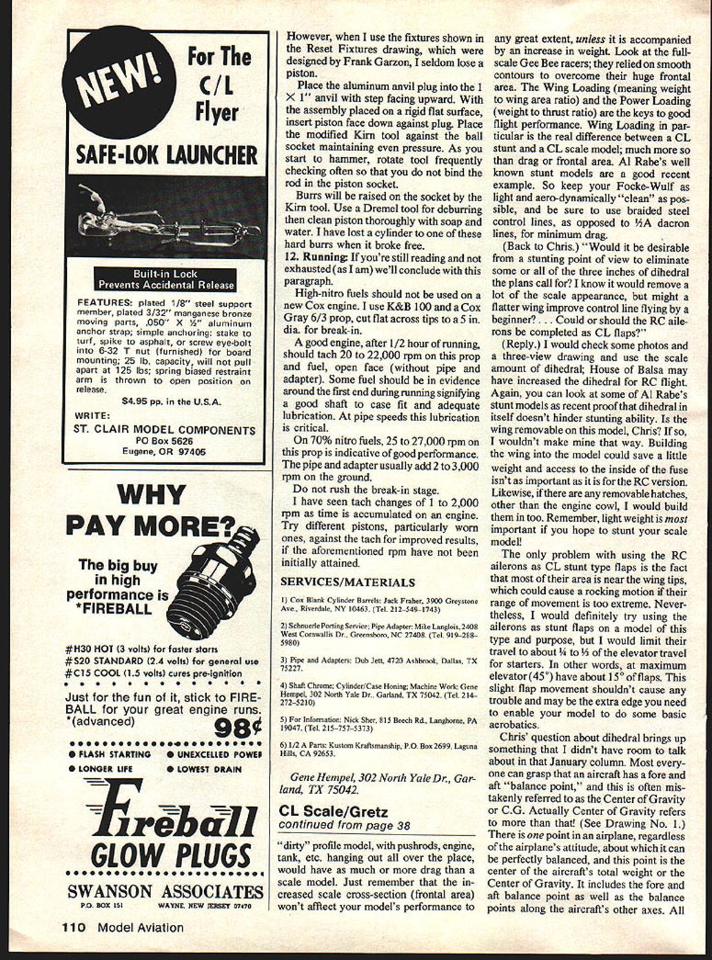
- Pipe Adapter
- This part is key to proper pipe performance and must be made correctly with no leaks.
- The material should be mild steel which closely matches the cylinder material thermally, thus preventing distortion when tightening.
- Contour the exhaust opening in the clamp for a good match to the cylinder exhaust. There is added rpm here.
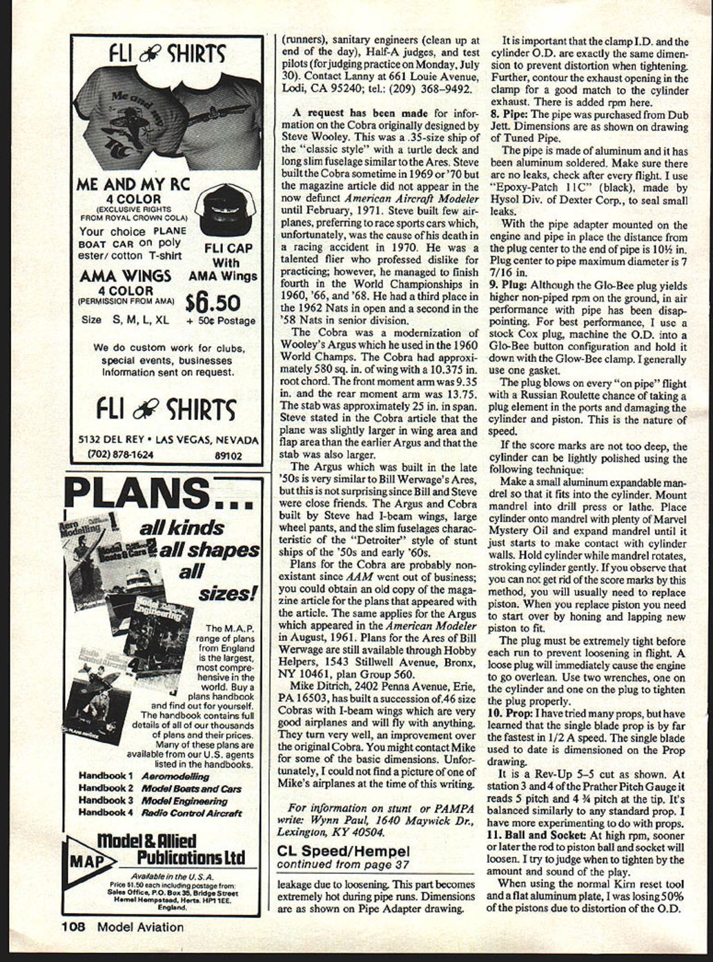
- Pipe
- The pipe was purchased from Dub Jett. Dimensions are as shown on the drawing of the tuned pipe.
- The pipe is made of aluminum and it has been aluminum-soldered. Make sure there are no leaks; check after every flight.
- I use "Epoxy-Patch 11C" (black), made by Hysol Div. of Dexter Corp., to seal small leaks.
- With the pipe adapter mounted on the engine and the pipe in place, the distance from the plug center to the end of the pipe is 10½ in.
- Plug center to pipe maximum diameter is 7/16 in.
- Plug
- Although the Glo-Bee plug yields higher non-piped rpm on the ground, in-air performance with pipe has been disappointing.
- For best performance, I use a stock Cox plug, machine the O.D. into a Glo-Bee button configuration and hold it down with the Glo-Bee clamp. I generally use one gasket.
- The plug blows on every "on pipe" flight with a Russian-Roulette chance of taking a plug element in the ports and damaging the cylinder and piston. This is the nature of speed.
- If the score marks are not too deep, the cylinder can be lightly polished using the following technique:
- Make a small aluminum expandable mandrel so that it fits into the cylinder. Mount mandrel into a drill press or lathe.
- Place the cylinder onto the mandrel with plenty of Marvel Mystery Oil and expand the mandrel until it just starts to make contact with cylinder walls.
- Hold the cylinder while the mandrel rotates, stroking the cylinder gently.
- If you cannot get rid of the score marks by this method, you will usually need to replace the piston. When replacing the piston you need to start over by honing and lapping the new piston to fit.
- The plug must be extremely tight before each run to prevent loosening in flight. A loose plug will immediately cause the engine to go overlean. Use two wrenches, one on the cylinder and one on the plug to tighten the plug properly.
- Prop
- I have tried many props, but have learned that the single-blade prop is by far the fastest in 1/2 A speed.
- The single blade used to date is a Rev-Up 5-5 cut as shown in the prop drawing.
- At station 3 and 4 of the Prather Pitch Gauge it reads 3 pitch and 4¼ pitch at the tip. It's balanced similarly to any standard prop.
- I have more experimenting to do with props.
- Ball and Socket
- At high rpm, sooner or later the rod-to-piston ball and socket will loosen. I try to judge when to tighten by the amount and sound of the play.
- When using the normal Kirn reset tool and a flat aluminum plate, I was losing 50% of the pistons due to distortion of the O.D. However, when I use the fixtures shown in the Reset Fixtures drawing, which were designed by Frank Garzon, I seldom lose a piston.
- Place the aluminum anvil plug into the 1 x 1" anvil with the step facing upward. With the assembly placed on a rigid flat surface, insert the piston face down against the plug. Place the modified Kirn tool against the ball socket maintaining even pressure. As you start to hammer, rotate the tool frequently, checking often so that you do not bind the rod in the piston socket.
- Burrs will be raised on the socket by the Kirn tool. Use a Dremel tool for deburring then clean the piston thoroughly with soap and water. I have lost a cylinder to one of these hard burrs when it broke free.
- Running
- High-nitro fuels should not be used on a new Cox engine. I use K&B 100 and a Cox Gray 6/3 prop, cut flat across tips to a 5 in. dia. for break-in.
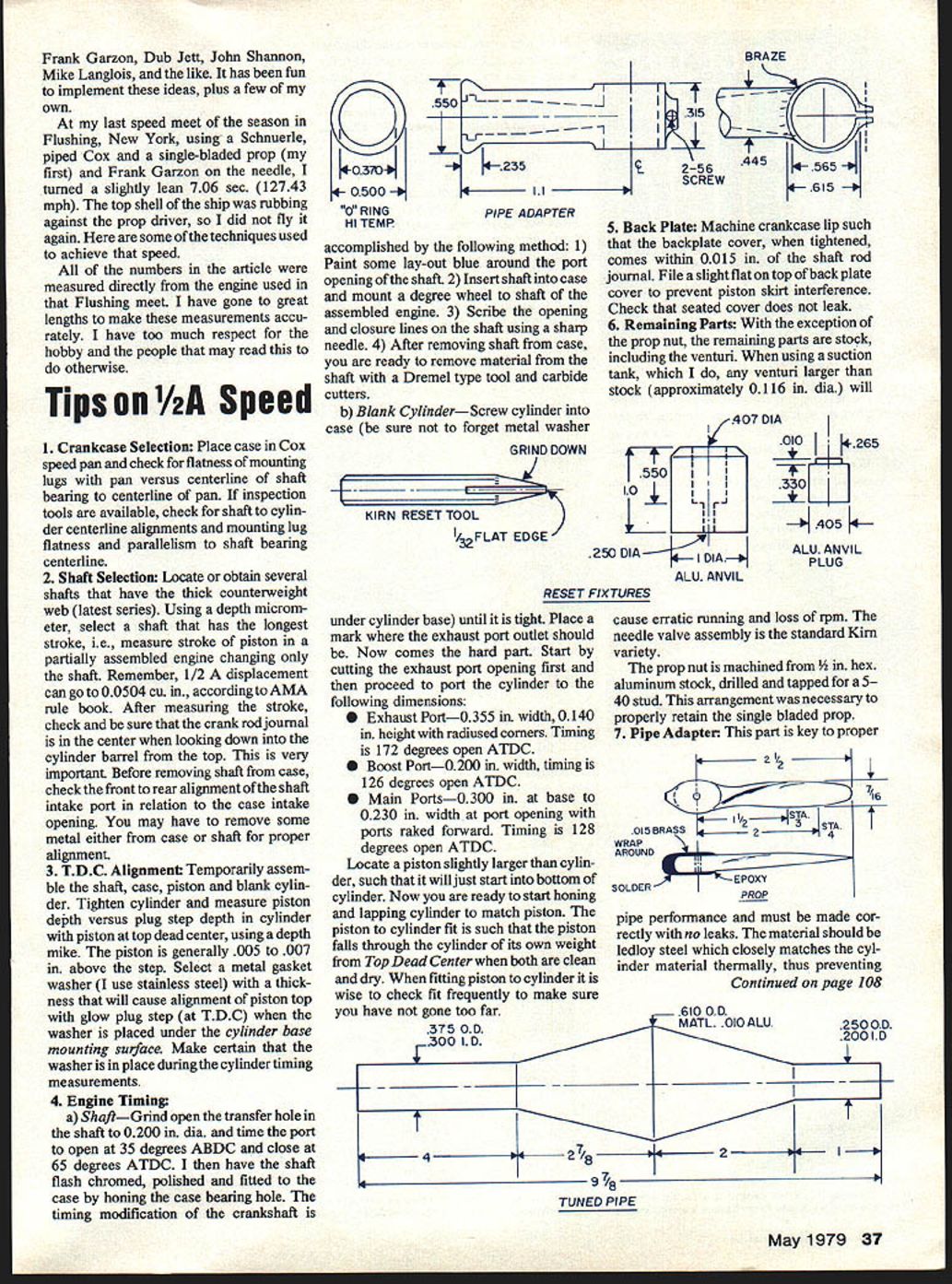
- A good engine, after 1/2 hour of running, should tach 20,000 to 22,000 rpm on this prop and fuel, open face (without pipe and adapter). Some fuel should be in evidence around the front end during running signifying a good shaft-to-case fit and adequate lubrication. At pipe speeds this lubrication is critical.
- On 70% nitro fuels, 25,000 to 27,000 rpm on this prop is indicative of good performance. The pipe and adapter usually add 2,000 to 3,000 rpm on the ground.
- Do not rush the break-in stage.
- I have seen tach changes of 1,000 to 2,000 rpm as time is accumulated on an engine. Try different pistons, particularly worn ones, against the tach for improved results, if the aforementioned rpm have not been initially attained.
Services/Materials
- Cox Blank Cylinder Barrels: Jack Fraher, 3900 Greystone Ave., Riverdale, NY 10461. Tel. 212-549-1743
- Schnuerle Porting Service; Pipe Adapter: Mike Langlois, 2408 West Cornwallis Dr., Greensboro, NC 27408. Tel. 919-288-5980
- Pipes and Adapters: Dub Jett, 4720 Ashbrook, Dallas, TX 75227
- Shaft Chrome; Cylinder/Case Honing; Machine Work: Gene Hempel, 302 North Yale Dr., Garland, TX 75042. Tel. 214-272-5210
- For information: Nick Sher, 815 Beech Rd., Langhorne, PA 19047. Tel. 215-757-5373
- 1/2 A Parts: Kustom Kraftsmanship, P.O. Box 2699, Laguna Hills, CA 92653
Gene Hempel 302 North Yale Dr., Garland, TX 75042
Transcribed from original scans by AI. Minor OCR errors may remain.

