
Control Line: Speed
Gene Hempel
Author's Note
I have received several letters concerning FAI control-line Speed. There appears to be a growing interest in this event. I hope this is an indicator that Speed will make a positive comeback.
Since there is more active interest in FAI Speed, I have asked Charles Lieber to write this month's column. Charles was a member of the 1978 FAI Speed team that was sent to England for the Championships. He placed fifth for overall performance. FAI Speed requires a dedicated speed modeler to overcome some problems that arise for which there seems, at times, no solution. I feel Charles is the type of person to bring to FAI Speed that special charisma.
By Charles Lieber
What is FAI Speed?
The rules for this event are simple:
- Engine displacement less than .1526 cu. in.
- Fuel is 80% methanol and 20% lubricant.
- Minimum total area is 77.55 sq. in. for a 1.5 engine.
- Maximum area loading is 17.64 oz. for a 1.5 engine.
- Line length is 52.2 ft.
- Aircraft must R.O.G. (rise off ground) and fly for two non-timed laps, plus ten timed laps after the pilot enters the pylon yoke.
- The aircraft must remain within a 3- to 10-ft. altitude band, and the control handle must not leave the pylon yoke.
Prior to entering the pylon, whipping is allowed.
Airplane design
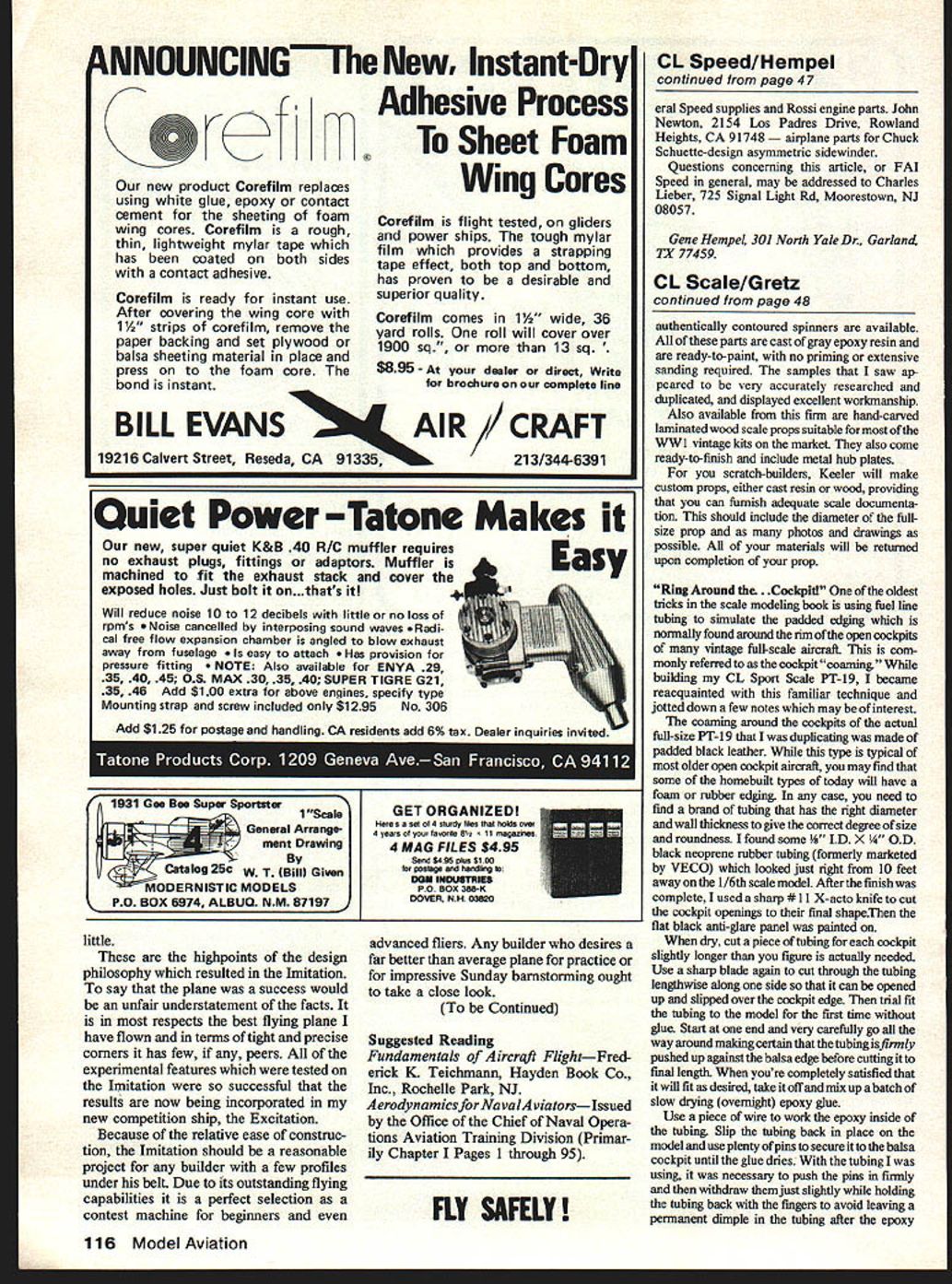
Design has evolved from upright-engine, symmetric planform layouts to the presently favored high-aspect-ratio asymmetric sidewinder designs of Chuck Schuette and asymmetric upright-engine designs of Emil Rumpel. My own airplane is a medium-aspect-ratio sidewinder.
The idea behind the high-aspect-ratio asymmetric design is to minimize drag as follows:
- Control-line drag by wing covering.
- Induced wing drag due to lift.
- Drag due to higher speed of outboard wing sections.
It is necessary to be very picky about airplane design, because all are flying to the same formula and top speeds are within a few tenths of a second of each other.
High-aspect-ratio wings do have penalties: they require accurate location of the C.G. and very careful piloting in windy weather.
Typical construction is similar to AMA types, using aluminum wings, wood or fiberglass bodies, and half pans. Recent wing construction developments include my own fiberglass design and an aluminum-clad balsa-core design by Rumpel. Both have been proven in competition.
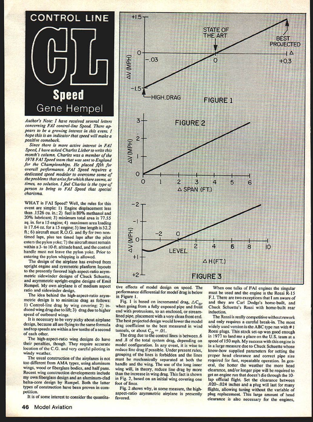
It is of interest to consider the quantitative effects of model design on speed. Figure 1 (not shown) is based on incremental drag, ΔC_D, when going from a fully exposed pipe and front end with protrusions to an enclosed or streamlined pipe placement with a very clean front end. The best projected design would lower the model drag coefficient to the best measured in wind tunnels, about C_drag = 0.01.
Drag due to the control lines is between 60% and 80% of the total system drag, depending on model configuration. It is wise to reduce line drag if possible. Under present rules, grouping of the lines is forbidden and the lines must be mechanically separated at both the handle and the wing. The use of a long inner wing will, in theory, reduce line drag by more than the increase in wing drag. This fact is illustrated in Figure 2 (not shown), based on an initial wing covering one foot of lines. Figure 2 shows why the high-aspect-ratio asymmetric airplane is presently favored to some extent.
Engines
When one talks of FAI engines the singular must be used: the engine is the Rossi R-15 F.I. There are two exceptions I am aware of: Carl Dodge's home-built engine, and Chuck Schuette's Rossi with a home-built rear induction.
The Rossi is competitive without heavy rework and only requires a careful break-in. The most widely used version is the ABC type run with #1 Rossi plugs. This stock set-up was good enough in 1977 to land me a place on the U.S. team at a speed of 150 mph. My success with this engine is largely due to Chuck Schuette, whose know-how supplied parameters for setting the proper head clearance and correct pipe size required for fast, repeatable operation.
In general, the hotter the weather, the more head clearance and/or longer pipe will be required to get an engine run that doesn't die through the 10-lap official flight. Set the clearance between .020 and .024 inches and a plug will last for many flights, allowing tuning without the variable of plug replacement. This large amount of head clearance is also necessary for engines, especially those with radical timing, to develop consistent maximum power.
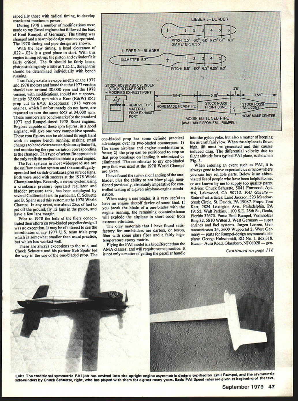
During 1978 a number of modifications were made to my Rossi engines following the lead of Emil Rumpel of Germany. The timing was changed and a new pipe design was incorporated. (1978 timing and pipe design are shown in the original article.)
With the new timing, a head clearance of .022–.024 in. is a good place to start. With this engine timing set-up, the piston and cylinder fit is fairly critical. The fit should be fairly loose—piston sticking only a little at T.D.C.—though this should be determined individually with bench running.
I ran extensive experiments on the 1977 and 1978 motors and found:
- The 1977 version should turn around 30,000 rpm.
- The 1978 version, with modifications, should run at approximately 32,000 rpm with a Kerr (K&W) 8x3 prop cut to 6x3.
- Exceptional 1978 engines are reported to turn the same 6x3 at 34,000 rpm.
These rpm figures are benchmarks for the standard 1977 and Rumpel-timed 1978 Rossi engines. Engines capable of these rpm figures, in a good airplane, will give very competitive speeds. These rpm figures can be obtained through hard work in engine bench running: making small changes to head clearance and piston-cylinder fit, and monitoring rpm variation corresponding to the changes. This scientific approach is the only realistic method to obtain a good engine.
Fuel systems
The most widespread fuel systems are the uniflow suction system and the centrifugally-operated fuel switch/crankcase-pressure designs. Both were used with success at the 1978 World Championships.
Recently, a newer system using a crankcase-pressure-operated regulator and a bladder pressure tank has been employed by several California fliers. In particular, C. Schuette and B. Spahr used this system at the 1978 World Champs.
Use about 25 cc of fuel to get off the ground, fly 12 laps in the pylon, and have a few laps margin.
Propellers
Prior to 1978 most fliers concentrated on two-bladed propeller design; I was no exception. It may be of interest to see the coordinates of my 1977 U.S. team trials prop (coordinates were given in the original article). That prop is somewhat smaller than usual practice but worked well.
There are always exceptions to the rule. Chuck Schuette and his partner Bob Spahr led the way in the use of the one-bladed prop. The one-blader has practical advantages over a two-blader:
- The same airplane and engine combination is faster.
- The prop can be positioned to stop so that prop breakage on landing is minimized or eliminated.
The coordinates to my one-bladed prop used at the 1978 World Champs are given in the original article.
Survival on landing of the one-blader, plus the ability to avoid blowing plugs (mentioned previously), are absolutely imperative for controlled testing of a given airplane-engine combination.
When using a one-blader, it is very useful to have an engine shutoff device. If you break the blade of a one-blader with the engine running, the remaining counterbalance will destroy the airplane quickly from extreme vibration.
The only materials I have found satisfactory for one-bladers are carbon or boron fiber with some glass fiber and a fairly high-temperature epoxy matrix.
Flying the FAI model
Flying an FAI model differs from AMA classes and requires practice. It's not only a matter of getting the peculiar handle into the pylon yoke, but also keeping the aircraft fairly low. When the airplane is flown high, lift must be generated and this causes induced drag. The differential velocity due to high altitude for a typical FAI plane is shown in Figure 3 (not shown).
Sources and suppliers
When entering an event such as FAI, it is good to have expert advice or know where you can buy reliable parts. Below is an abbreviated list of people who have been helpful to me or are known to supply top-quality parts:
- Advice: Chuck Schuette, 5041 Fanwood, Apt. #4, Lakewood, CA 90713.
- FAI Gazette — state-of-the-art articles: Laird Jackson, 523 Meadowbrook Circle, St. Davids, PA 19087.
- Props: Tom Kerr, 7824 Lexington Ave., Philadelphia, PA 19152.
- Props: Walt Perkins, 1100 S.E. 28th St., Ocala, FL 32670.
- Parts and engines: Emil Rumpel, Vormholzer Ring 32, 5810 Witten 3, West Germany — super engines and fuel systems.
- Parts for Rumpel-design asymmetric airplane: Jurgen Lenzen, Germany.
- General speed supplies and Rossi engine parts: George Hulscheidt, RD No. 1, Box 318, Ewan-Aura Road, Glassboro, NJ 08028.
- Airplane parts for Chuck Schuette–design asymmetric sidewinder: John Newton, 2154 Los Padres Drive, Rowland Heights, CA 91748.
Questions concerning this article, or FAI Speed in general, may be addressed to:
- Charles Lieber, 725 Signal Light Rd., Moorestown, NJ 08057.
- Gene Hempel, 301 North Yale Dr., Garland, TX 77459.
Transcribed from original scans by AI. Minor OCR errors may remain.

