

CONTROL LINE SPEED
Dave Mark, Box 371, Fenton MI 48430; E-mail: Speedtimes@chartermi.net
Introduction
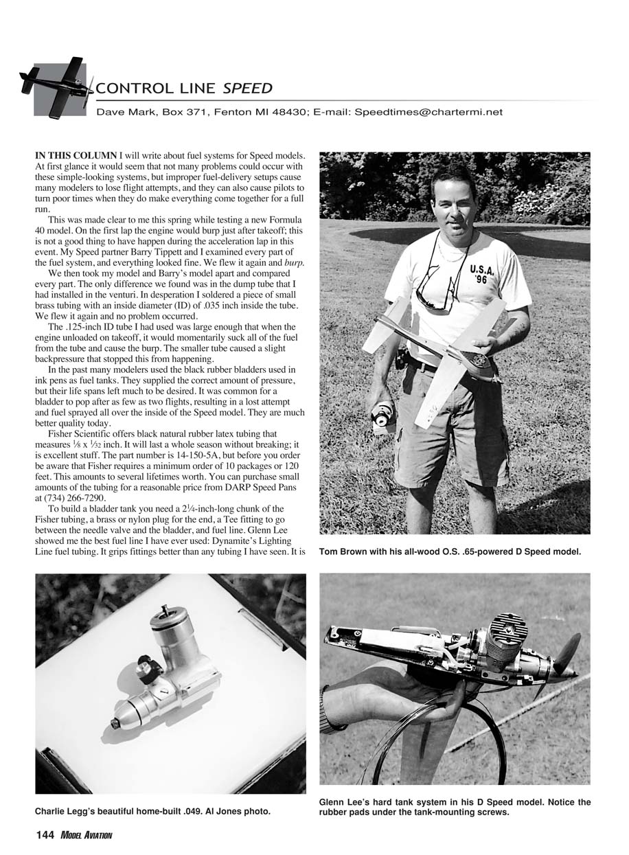
In this column I will write about fuel systems for Speed models. At first glance it would seem that not many problems could occur with these simple-looking systems, but improper fuel-delivery setups cause many modelers to lose flight attempts, and they can also cause pilots to turn poor times when they do make everything come together for a full run.
This was made clear to me this spring while testing a new Formula 40 model. On the first lap the engine would burp just after takeoff; this is not a good thing to have happen during the acceleration lap in this event. My Speed partner Barry Tippett and I examined every part of the fuel system, and everything looked fine. We flew it again and it burped.
We then took my model and Barry’s model apart and compared every part. The only difference we found was in the dump tube that I had installed in the venturi. In desperation I soldered a piece of small brass tubing with an inside diameter (ID) of .035 inch inside the tube. We flew it again and no problem occurred.
The .125-inch ID tube I had used was large enough that when the engine unloaded on takeoff it would momentarily suck all of the fuel from the tube and cause the burp. The smaller tube caused a slight backpressure that stopped this from happening.
Bladder Tanks
In the past many modelers used the black rubber bladders used in ink pens as fuel tanks. They supplied the correct amount of pressure, but their life spans left much to be desired. It was common for a bladder to pop after as few as two flights, resulting in a lost attempt and fuel sprayed all over the inside of the Speed model. They are much better quality today.
Fisher Scientific offers black natural rubber latex tubing that measures 1/8 x 1/32 inch. It will last a whole season without breaking; it is excellent stuff. The part number is 14-150-5A, but before you order be aware that Fisher requires a minimum order of 10 packages or 120 feet. This amounts to several lifetimes’ worth. You can purchase small amounts of the tubing for a reasonable price from DARP Speed Pans at (734) 266-7290.
Materials and construction
To build a bladder tank you need:
- A 2-1/4-inch-long chunk of the Fisher tubing
- A brass or nylon plug for the end
- A Tee fitting to go between the needle valve and the bladder
- Fuel line
Glenn Lee showed me the best fuel line I have ever used: Dynamite’s Lightning Line fuel tubing. It grips fittings better than any tubing I have seen. It is distributed by Horizon Hobby, Inc. (www.horizonhobby.com). All of the joints will need to be wrapped to hold everything together. A wide variety of items, from tie wraps to wire, are used in this area. I prefer 25-pound-test woven nylon fishing line. The woven line is easy to work with, doesn't stretch when wet with fuel, and does not have any sharp ends that might poke holes in the tank during a run.
Protecting the bladder
The next step is to install a cover that will protect the bladder from the hot pan. Two items that can be used:
- Woven-cotton finger-wrap bandage (available at the drugstore). Cut off a 1-1/2-inch-long piece of bandage, open it up, and slide it over the Fisher tubing. Wrap the bandage material with fishing line at the tee to keep it from sliding off during use. Leave the other end open.
- A toy balloon. Cut the end off the balloon, then dip it in glycerin to lubricate it when it slides over the outside of the tank.
Training the tank
The last, important step is to train the tank to inflate from the front to the back. If you do not do this, the tank will fill from back to front and pinch the line off, resulting in no fuel and no flight.
Steps:
- Take hold of the tank from the rear and allow approximately 1/4 inch of the black tubing to be free, then pinch the tubing off.
- Inflate this 1/4 inch with air from your empty fuel syringe.
- After doing this, the bladder will stay up under the tank to act as a spacer when you install it on the pan.
To mount the tank to the pan, drill out the pan screw holes and back them up with a small rubber pad so the tank doesn't crush when tightened into place. A small-diameter screw with a large flat head works well.
Always fill from the front to the back. A bladder constructed as described will easily hold 45 cubic centimeters of fuel for a Formula 40 or for the .21 events.
One interesting thing a bladder fuel system will do is let you know if you had the proper set on your flight. This will happen on the last lap of your flight. If you have the ideal set on the valve, the engine will go slightly rich as the pressure rises slightly in the bladder, forcing the last bit of fuel out. If the set is too lean, the engine will gain in revolutions just before it quits.
Hard (metal) tanks
The final tank system that I wanted to cover is the hard tank. I like to use this type of tank only on larger models where the slow increase in pressure across a run is less critical. Hard tanks can be made from several materials. The most common today are fiberglass or machined aluminum. Glass tanks may be formed over a male plug and then coated on the inside with epoxy to seal the surface.
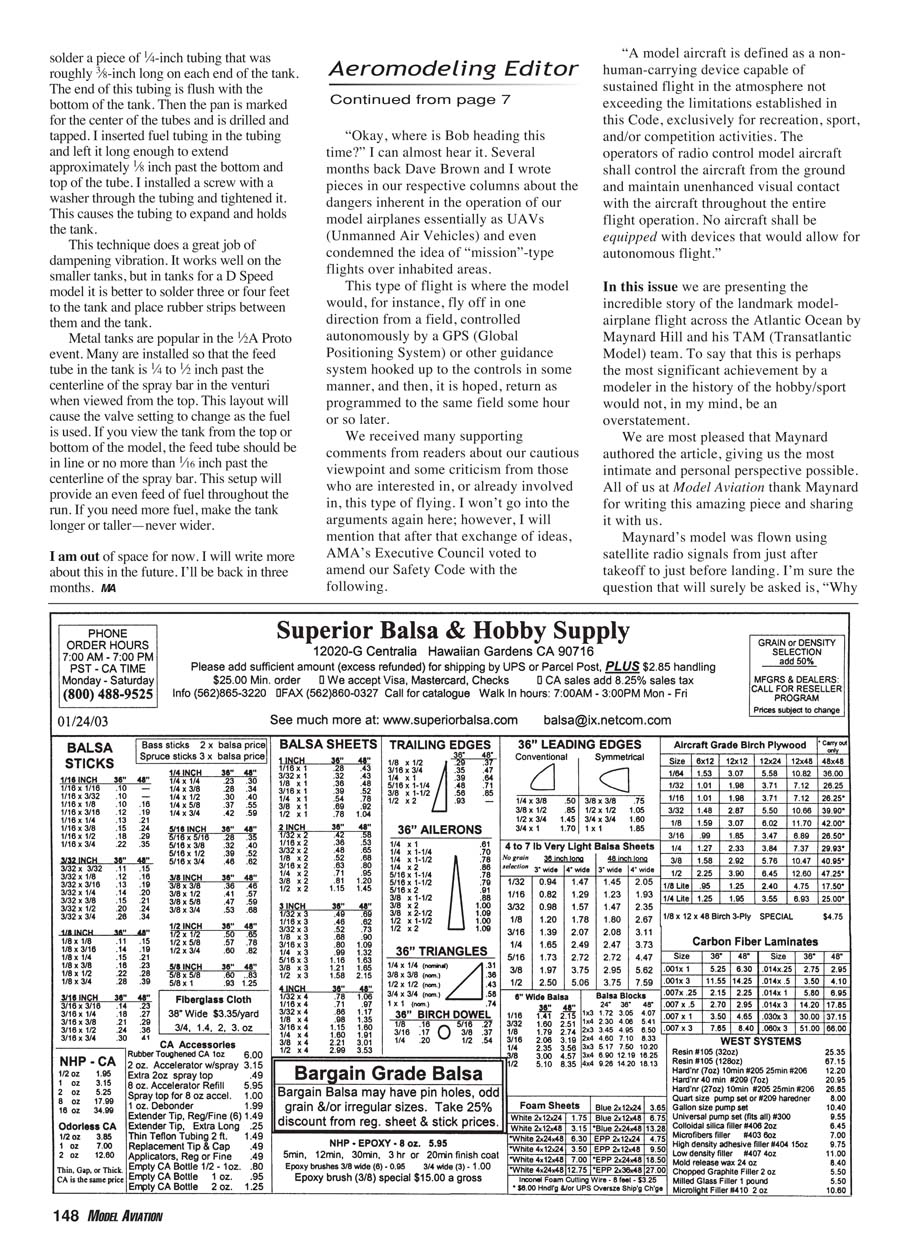
A machined aluminum tank offers a solid, permanent solution but may add a lot of weight. If you use an aluminum tank, remember to coat the inside with epoxy to prevent corrosion. The mounting of hard tanks requires some thought. I wrap a small pad of rubber under the tank-mounting screws to keep the tank from being crushed when the screws are tightened. This pad can be a piece of inner tube or an O-ring.
In a hard-tank system, the fill lines are plugged off and fuel is forced to the spray bar with crankcase pressure. Many erratic engine runs are caused by too large a hole in the pressure nipple that is installed in the backplate or backplate bolt holes. The recommended size hole for a pressure fitting is 0.015 inch, but that is quite small and many find it hard to make a fitting that little.
Making a small pressure hole
The easiest method I have found for making a hole this size is to drill a 1/32-inch hole through the pressure fitting, then use soft solder to close the end of the hole. Before you do that, insert a piece of 0.015-inch control line a short way into the fitting. Screw the fitting into a small waste block of steel or use a C-clamp to hold the fitting. Grab the loose wire in the drill chuck of your drill press or clamp the wire to something so that the block is roughly 1/2 inch in the air. Turn your soldering iron on and let it heat up. When it is hot, touch it to the wire near the pressure fitting. This will heat the wire and just melt the solder in the fitting, letting it drop off of the wire. You end up with a fitting that has a clean, small hole in it.
You should install a fuel-check valve in the pressure line to the tank. This will allow the tank to be filled without flooding the engine by forcing fuel through the pressure fitting.
Tank mounting and leak prevention
When I first started flying Speed a few years ago, I used metal tanks in everything. During this time I often commented that I did not need tin-plate stock to build my tanks; I just carved my tanks from a solid block of solder.
It seemed that after just a few flights there would be a leak. It was to the point that I took a glass jar and water to every contest to leak-test my tank. I also carried a butane-powered soldering iron. It was soon pointed out to me that the reason for all of the leaks was that I had improperly mounted the metal tank in the model. I had built the tank so that it would be pinched between the top and the pan, which allowed it to vibrate and crack.
I built a new tank and tried the simple method of embedding it in a few rows of silicone caulk. This helped tremendously, and my speeds picked up as a result. The problems I encountered with this method were two-fold. First, the caulk would slowly degrade from fuel and need to be picked out and replaced. Second, if a leak did occur, the tank would need to be dug out of the caulk bed, cleaned, soldered, and reset. This is a messy, slow process at best.
The next improvement was to vertically solder a piece of 1/4-inch tubing, roughly 3/8-inch long, on each end of the tank. The end of this tubing is flush with the bottom of the tank. Then the pan is marked for the center of the tubes and is drilled and tapped. I inserted fuel tubing in the tubing and left it long enough to extend approximately 1/8 inch past the bottom and top of the tube. I installed a screw with a washer through the tubing and tightened it. This causes the tubing to expand and holds the tank.
This technique does a great job of dampening vibration. It works well on the smaller tanks, but in tanks for a D Speed model it is better to solder three or four feet to the tank and place rubber strips between them and the tank.
Metal tanks are popular in the 1/2A Proto event. Many are installed so that the feed tube in the tank is 1/8 to 1/4 inch past the centerline of the spray bar in the venturi when viewed from the top. This layout will cause the valve setting to change as the fuel is used. If you view the tank from the top or bottom of the model, the feed tube should be in line or no more than 1/16 inch past the centerline of the spray bar. This setup will provide an even feed of fuel throughout the run. If you need more fuel, make the tank longer or taller—never wider.
Closing
I am out of space for now. I will write more about this in the future. I'll be back in three months.
— Dave Mark
Transcribed from original scans by AI. Minor OCR errors may remain.

