
Control Line: SPEED
Gene Hempel
Engine Set-Up
- Disassemble your X-29 except for the bearings.
- Heat the case in an oven to approximately 350°F to ease bearing removal. You may have to rap the case on a piece of wood so the bearings will fall out.
- Allow the bearings to cool, then clean thoroughly in lacquer thinner and dry. If you have an ultrasonic cleaner, use it.
- Wear heavy gloves to avoid burns while handling the hot case.
- After the case has cooled slightly, insert the shaft and give it a fast spin. The shaft should spin freely and stop with the heavy part of the counterbalance at the bottom of the case.
- If there is any misalignment of bearings, reheat the case with the crankshaft inserted in the bearings. Allow the case to cool slightly, place an old prop on the shaft and tighten the prop nut, then spin the crankshaft. This should align the bearings to the crankshaft.
- There should be no binds; binds can rob the engine of up to 1000–1500 rpm.
- With the crankshaft assembly complete, oil with Marvel Mystery Oil or 3-In-1 Oil, wrap up, and set aside.
Back Plate and Rotor
- Remove the rotor from the back plate.
- Carefully examine the back plate for metal flashing around the edges. Use an X-Acto knife (#11 blade) to remove any flashing from the face and edges.
- Obtain a piece of tempered glass, about 12–14 inches square, to use as a lapping plate.
- Place a piece of #600 grit wet-or-dry sandpaper on the glass and pour a small amount of 3-In-1 Oil on the sandpaper.
- Sand the face of the back plate in a circular motion until the running surface is smooth and has a gray appearance.
- Clean the back plate, rotor, and rotor pin with liquid soap and water. Dip parts in lacquer thinner and let dry thoroughly.
- Reassemble back plate and rotor:
- Place two strips of .006-inch feeler-gauge material between rotor and back plate.
- Press rotor pin against rotor until you have a snug fit, then tighten the rotor pin set screw.
- Place several drops of Marvel Mystery Oil or 3-In-1 Oil on the rotor and check for binds.
- If it feels OK, wrap up and set aside.
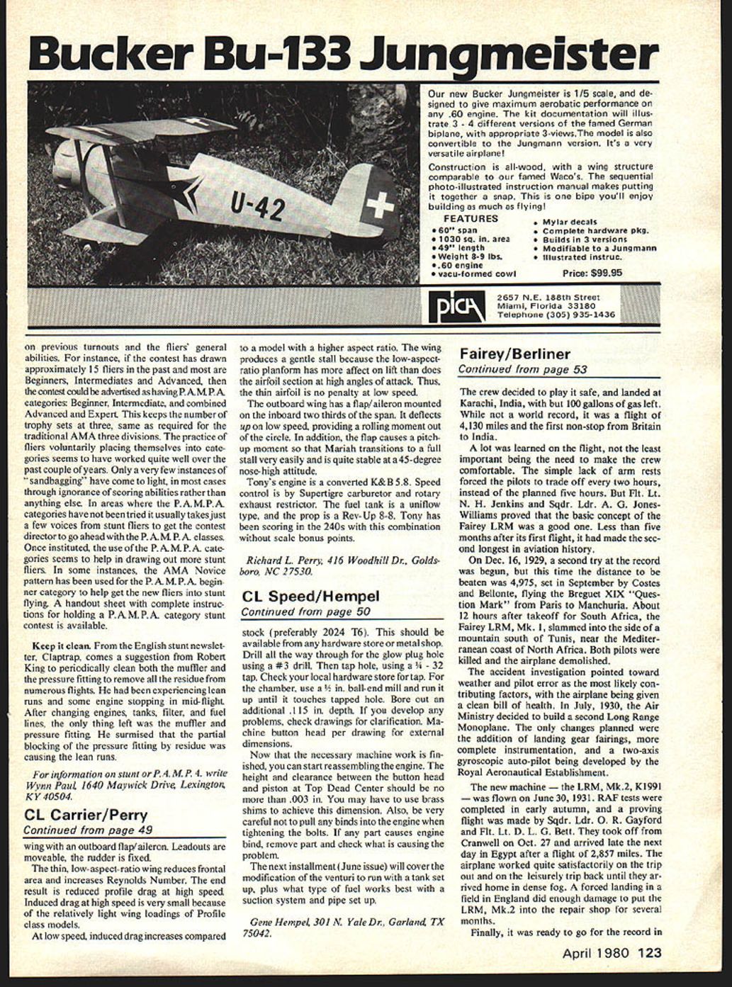
Sleeve and Piston Rework
- You will need access to a lathe.
- Machine .014 inches from the bottom side of the sleeve flange. This allows the sleeve to drop deeper into the case to correct sleeve timing (stock X-29 timing is 178° exhaust, 138° intake; target timing is 173° exhaust, 133° intake).
- Piston-to-sleeve fit is critical:
- Carefully remove wrist pin and rod from the piston and set aside.
- Clean sleeve and piston with liquid soap and water (a toothbrush works well). Dip parts in lacquer thinner to displace any moisture. Dry thoroughly and blow off lint and loose particles.
- Turn the sleeve bottom side up. Drop the piston into the sleeve and let it fall by its own weight. The piston should stop approximately .250 inches from the top of the sleeve.
- Using a 1/8-inch wood dowel, push the piston very lightly through the sleeve; this should give a very good piston seal.
- If the piston falls through the sleeve, the fit is too loose — the engine will not run well. Have the sleeve rechromed or find another piston that fits.
- If the sleeve is too tight, lap the piston to the sleeve.
- Lapping:
- A mixture of Comet and 3-In-1 Oil makes an excellent lapping compound.
- Be extremely careful — clean parts thoroughly and check the piston fit frequently rather than guessing.
- If you need sleeve rechroming and honing quotes, send a SASE to: Gene Hempel, 301 N. Yale Drive, Garland, TX 75042.
- Reassemble wrist pin and rod to piston, oil parts thoroughly, and set aside.
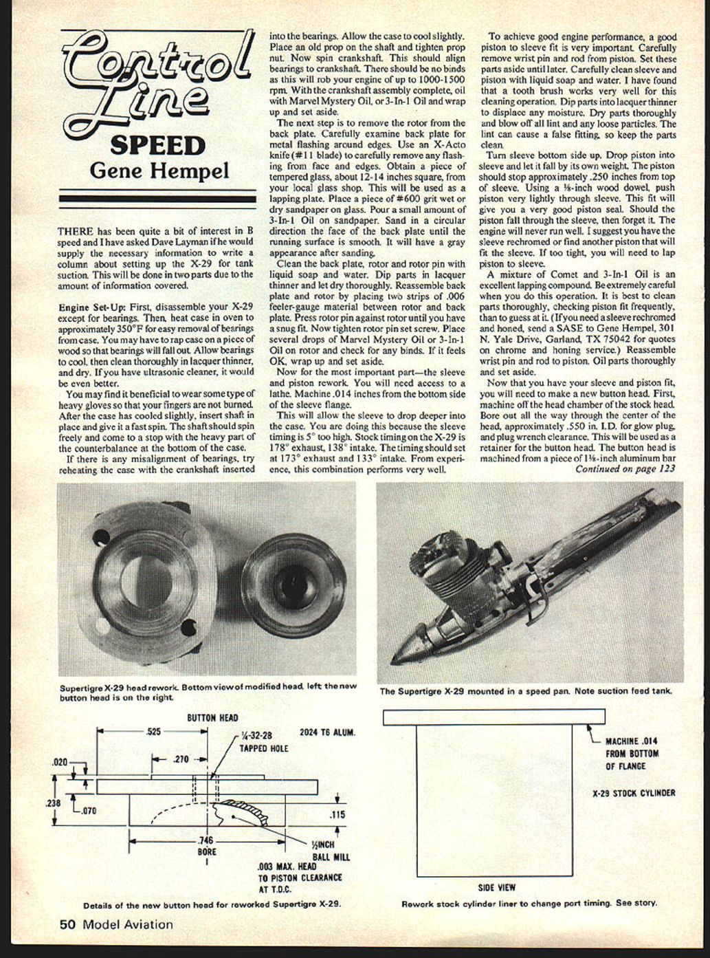
Button Head and Final Assembly
- Make a new button head:
- Machine off the head chamber of the stock head.
- Bore out the way through the center of the head to approximately .550 in. I.D. for glow-plug clearance. This will be used as a retainer for the button head.
- The button head is machined from a piece of 1-1/4-inch aluminum bar stock (preferably 2024-T6). This should be available from any hardware store or metal shop.
- Drill all the way through for the glow-plug hole using a #3 drill, then tap the hole with a 4-32 tap (check your local hardware store for the tap).
- For the chamber, use a 3/8-inch ball-end mill and run it up until it touches the tapped hole; bore out an additional .115 inch depth.
- Machine the button head per drawing for external dimensions. If problems develop, check the drawings for clarification.
- Reassembly:
- The height and clearance between the button head and piston at Top Dead Center should be no more than .003 inch. You may need shims to achieve this dimension.
- Be careful not to introduce any binds when tightening bolts. If any part causes engine bind, remove the part and determine the cause.
Next Installment
The next installment (June issue) will cover modification of the venturi to run with a tank setup, plus recommended fuels for a suction system and pipe setup.
Gene Hempel 301 N. Yale Dr. Garland, TX 75042
Transcribed from original scans by AI. Minor OCR errors may remain.

