
Control Line: Speed
Gene Hempel
This column continues the article from the April issue. We are describing the rework needed to set up the Supertigre X-29 for suction fuel feed. I hope, by the time you read this, all the previously described engine rework is finished.
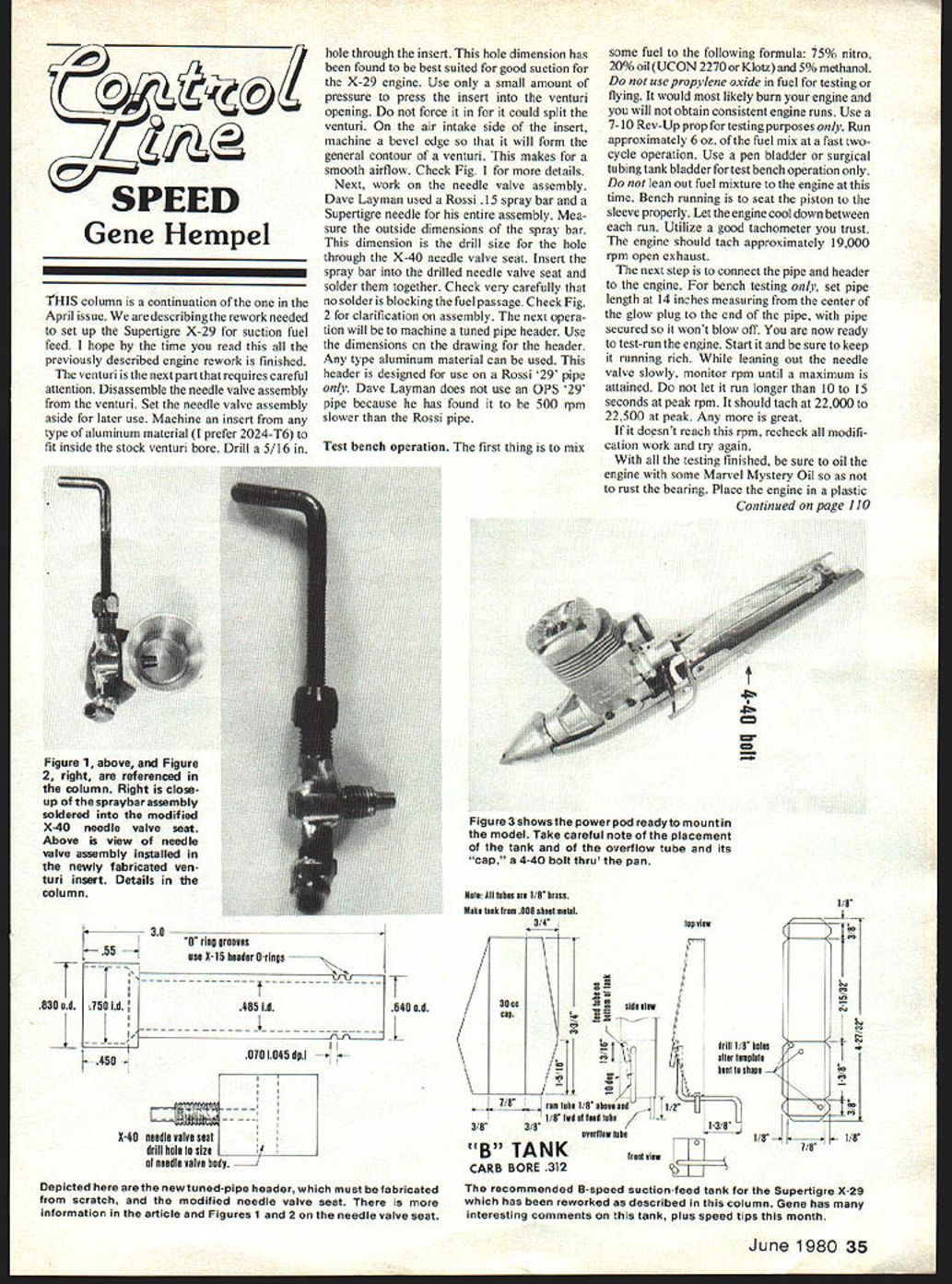
Venturi modification
- Disassemble the needle valve assembly from the venturi and set the needle valve assembly aside for later use.
- Machine an insert from any type of aluminum material (2024-T6 preferred) to fit inside the stock venturi bore.
- Drill a 5/16 in. hole through the insert. This hole dimension has been found to provide good suction for the X-29 engine.
- Press the insert into the venturi opening using only a small amount of pressure. Do not force it in, as the venturi could split.
- On the air intake side of the insert, machine a bevel edge so it forms the general contour of a venturi for smooth airflow. (See Fig. 1.)
Needle valve assembly
- Dave Layman used a Rossi .15 spray bar and a Supertigre needle for his assembly.
- Measure the outside diameter of the spray bar; this dimension is the drill size for the hole through the X-40 needle valve seat.
- Insert the spray bar into the drilled needle valve seat and solder them together.
- Check very carefully that no solder is blocking the fuel passage. (See Fig. 2 for assembly clarification.)
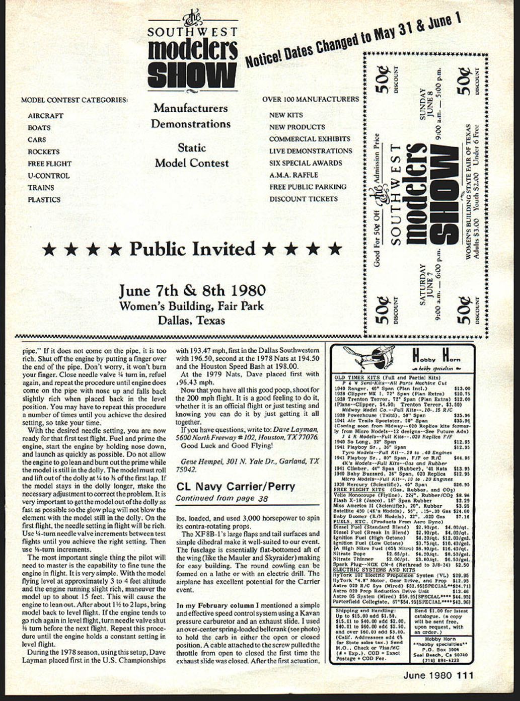
Tuned pipe header
- Machine a tuned pipe header to the dimensions on the drawing. Any aluminum can be used.
- This header is designed for a Rossi '29' pipe only. Dave Layman does not use an OPS '29' pipe because he has found it to be about 500 rpm slower than the Rossi pipe.
Test bench operation
- Fuel mix: 75% nitro, 20% oil (UCON 2270 or Klotz), 5% methanol. Do not use propylene oxide in fuel for testing or flying — it will likely burn your engine and give inconsistent runs.
- Use a 7-10 Rev-Up prop for testing only.
- Run approximately 6 oz. of the fuel mix at a fast two-cycle operation. Use a pen bladder or surgical tubing tank bladder for test-bench operation only. Do not lean out the fuel mixture at this time — bench running is to seat the piston to the sleeve properly.
- Let the engine cool between runs. Use a trustworthy tachometer. The engine should tach approximately 19,000 rpm on open exhaust.
Next, connect the pipe and header to the engine for bench testing only. Set pipe length at 14 inches, measuring from the center of the glow plug to the end of the pipe, and secure the pipe so it won't blow off. Start the engine and keep it running rich. While slowly leaning the needle valve, monitor rpm until a maximum is attained. Do not let it run longer than 10–15 seconds at peak rpm. It should tach at 22,000–22,500 rpm at peak; more is acceptable. If it doesn't reach this rpm, recheck all modifications and try again.
After testing, oil the engine with some Marvel Mystery Oil to prevent bearing rust. Place the engine in a plastic bag and set it aside. This completes the engine modification instructions.
Suction tank (B speed) advantages
The suction tank in "B" speed has been a blessing compared to pen bladders. In the past, using pen bladders with pipe engines often yielded only one run per engine. The return to the tank system has made "B" speed fun to fly again.
Tank construction
- Study the drawing for tank construction carefully and do not deviate from it — the system works exceptionally well as designed.
- Radius all bends in the tubing to eliminate flat spots or kinks. Avoid pinching the tubing with pliers.
- Feed tube position: solder feed tube in at approximately a 10 degree angle up from horizontal. Ensure the feed tube points straight to the spray bar elbow; you may need to resolder the elbow to align it with the feed tube.
- Clean the inside of the finished tank thoroughly with lacquer thinner. Pressure-check the tank for leaks.
Fitting the tank into the speed pan
- Use a hand grinder or mill to remove unnecessary metal so the fuel tank will fit.
- Take care that the tank mounts level and straight. Check tank height so it does not interfere with the model's control system.
- Clean the pan thoroughly with soap and water, then rinse with lacquer thinner or alcohol to displace moisture.
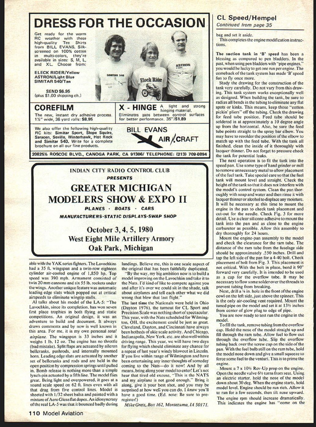
- Mount the engine in the pan to check tank placement and cut-out for the needle (see Fig. 3).
- Use a clear silicone adhesive to mount the tank in the pan and as close to the engine carburetor as possible. Allow this assembly to dry thoroughly for 24 hours.
Mount the engine-pan assembly to the model and check the clearance for the ram tube. The distance of the ram tube from the fuselage side should be approximately 0.550 inches.
Drill and tap the left side of the pan for a 4-40 bolt (placement per Fig. 3; not critical). With the bolt in place, bend it 90° carefully — it will be used as a cap for the overflow tube. You may need to flow some solder over the threads to prevent tubing from breaking.
Cowl vent and pipe set-up
- Drill a 1/16 in. hole in the front of the cowl on the left side, just above the spinner. This is the only air-cooling vent required.
- Mount the tuned pipe on the model and set it at 13-1/2 inches from the center of the glow plug to the edge of the pipe.
Filling, priming, and starting in the model
- To fill the tank, remove the tubing from the overflow cap. Hold the nose of the model straight up and fill through the ram tube. Allow fuel to flow out through the overflow tube. Replace the overflow tubing over the screw cap on the side of the pan.
- With the fuel bulb still on the ram tube, hold the model nose down and give a small squeeze to force some fuel to the venturi — this primes the engine.
- Mount a 7 x 10⁻¹/2 Rev-Up prop on the engine. Open the needle valve 6-1/2 turns from the seat.
- Using an electric starter, hold the nose of the model down about 30°. When the engine starts, hold the model level and run rich for a few seconds, then lift the nose upward. The engine rpm should increase dramatically — this indicates the engine has "come on the pipe."
- If it does not come on the pipe, it is too rich. Shut off the engine by placing a finger over the end of the pipe (it will not burn your finger). Close the needle valve 1/4 turn in, refuel/prime, and repeat until the engine comes on the pipe with the nose up and falls back slightly rich when returned to level.
You may need to repeat this procedure several times until the desired setting is achieved, so take your time.
First test flight
- Fuel and prime the engine, start it by holding nose down, and launch as quickly as possible. Do not allow the engine to go lean and burn out the prime while the model is still on the dolly.
- The model must roll and lift out of the dolly by 1/2 to 3/4 of its first lap. If it stays in the dolly longer, make necessary corrections. It is very important to get the model out quickly so the glow plug is not the thermal element while the model is still in the dolly.
- On the first flight, the needle setting in flight will be rich. Use 1/4-turn needle valve adjustments between test flights until you are near correct, then switch to 1/16-turn increments.
In-flight tuning
- The most important skill the pilot needs is tuning the engine in flight. Procedure: fly level at approximately 3–4 feet altitude with the engine slightly rich, then maneuver the model up to about 15 feet. This will lean the engine out.
- After about 1-1/2 to 2 laps, return to level flight. If the engine runs rich again in level flight, close the needle valve 1/8 turn before the next flight. Repeat until the engine holds a constant setting in level flight.
Competition results
During the 1978 season, using this setup, Dave Layman achieved:
- 1st in the U.S. Championships: 193.47 mph
- 1st in the Dallas Southwestern: 196.50 mph
- 2nd at the 1978 Nats: 194.50 mph
- Houston Speed Bash: 198.00 mph
At the 1979 Nats, Dave placed 1st with 196.43 mph.
Now that you have all this information, shoot for the 200 mph flight. It is a great feeling to do it, whether official or just testing and knowing you can do it.
Contact
- Questions to: Dave Layman, 5600 North Freeway #102, Houston, TX 77076.
- Author: Gene Hempel, 301 N. Yale Dr., Garland, TX 75042.
Good luck and good flying!
Transcribed from original scans by AI. Minor OCR errors may remain.

