
Control Line: Speed
Gene Hempel
This month's column covers the second and final part of Jerry Bradshaw's article "How to Construct a 1/2A Pipe." The first part appeared in the April 1981 issue.
After practicing on soldering aluminum and burning my fingers, I wonder if "Hot Stuff" withstands heat! With burning fingers, then, let's move on to the finishing of that pipe.
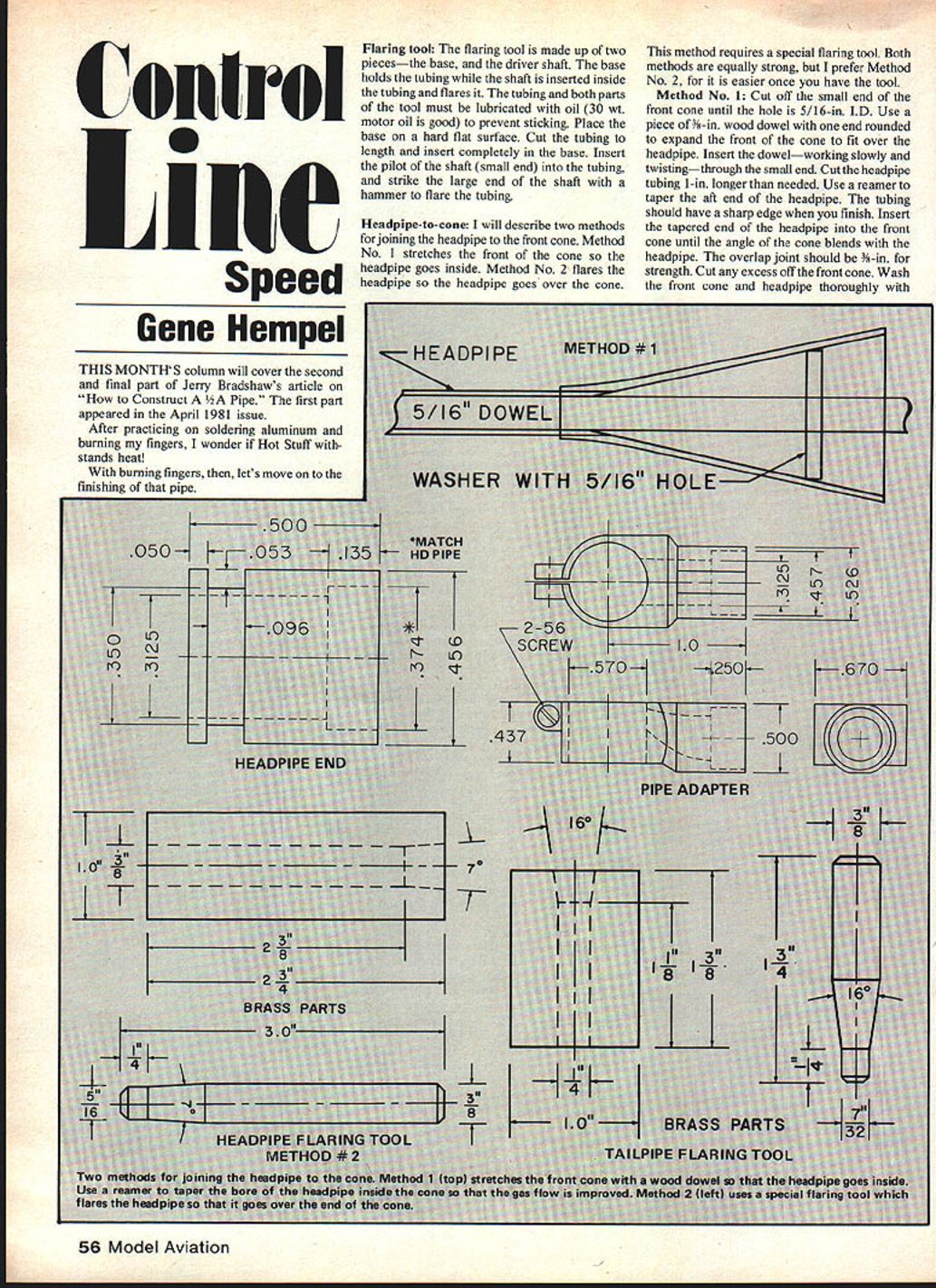
Flaring tool
The flaring tool is made up of two pieces — the base and the driver shaft. The base holds the tubing while the shaft is inserted inside the tubing and flares it. The tubing and both parts of the tool must be lubricated with oil (30 wt. motor oil is good) to prevent sticking.
Procedure:
- Place the base on a hard, flat surface.
- Cut the tubing to length and insert it completely in the base.
- Insert the pilot (small end) of the shaft into the tubing.
- Strike the large end of the shaft with a hammer to flare the tubing.
Headpipe-to-cone
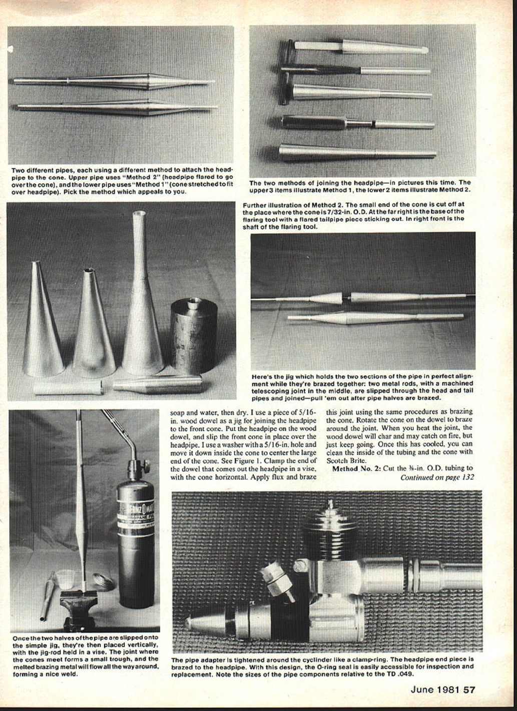
I will describe two methods for joining the headpipe to the front cone. Method No. 1 stretches the front of the cone so the headpipe goes inside. Method No. 2 flares the headpipe so the headpipe goes over the cone. Both methods are equally strong; I prefer Method No. 2 because it is easier once you have the tool.
- Method No. 1 (cone stretched to accept headpipe)
- Cut off the small end of the front cone until the hole is 5/16‑in. I.D.
- Use a piece of 5/16‑in. wood dowel with one end rounded to expand the front of the cone to fit over the headpipe. Insert the dowel slowly, twisting, through the small end.
- Cut the headpipe tubing 1 in. longer than needed.
- Use a reamer to taper the aft end of the headpipe; the tubing should have a sharp edge when finished.
- Insert the tapered end of the headpipe into the front cone until the angle of the cone blends with the headpipe. The overlap joint should be 3/8‑in. for strength. Cut any excess off the front cone.
- Wash the front cone and headpipe thoroughly with soap and water, then dry.
- Use a piece of 5/16‑in. wood dowel as a jig for joining the headpipe to the front cone: put the headpipe on the dowel, slip the front cone in place over the headpipe, and move a washer with a 5/16‑in. hole down inside the cone to center the large end of the cone (see Figure 1).
- Clamp the dowel so the end coming out of the headpipe is held in a vise, with the cone horizontal. Apply flux and braze the joint using the same procedures as brazing the cone. Rotate the cone on the dowel to braze around the joint. The dowel will char and may catch fire while heating; continue until brazing is completed.
- Once cooled, clean the inside of the tubing and cone with Scotch‑Brite.
- Method No. 2 (headpipe flared to slip over cone)
- Cut the 3/8‑in. O.D. tubing to 2‑3/4‑in. long.
- Flare one end of the tubing using the flaring tool.
- Cut the small end of the cone off where the cone is 5/16‑in. O.D.
- Use a taper reamer to put a sharp edge on the front of the cone.
- The headpipe should fit the cone snugly without rocking; therefore no jig is required when brazing.
- Clean the cone and headpipe with soap and water, then dry.
- Position the headpipe on the small end of the cone, place the base of the cone on a flat surface, and braze the joint using the same procedure as described before.
- After the cone cools, wash with soap and water to remove the flux.
Tailpipe-to-cone
- Cut the 7/32‑in. I.D. tubing to 1‑3/16‑in. long.
- Cut the small end of the cone off where the cone is 7/32‑in. O.D.
- The tailpipe should fit the cone snugly without rocking; therefore no jig is required when brazing.
- Clean the cone and tailpipe with soap and water, then dry.
- Position the tailpipe on the small end of the cone, place the base of the cone on a flat surface, and braze the tailpipe to the cone using the same procedures as described before.
- Use a taper reamer, working inside the cone, to enlarge the hole to 7/32‑in. I.D.
Final assembly
I have a very simple jig that holds the two sections of the pipe in perfect alignment while they are being brazed. The jig is made from two metal rods, one 5/16‑in. O.D. and one 3/16‑in. O.D., each at least 12 in. long. In one end of the 5/16‑in. rod, center‑drill a 3/16‑in. hole 1 in. deep (this should be done in a lathe).
- The large diameter end of the front cone should be slightly smaller than the large diameter of the rear cone; cut or file the large end of the front cone so it will just fit inside the large end of the rear cone.
- Clean all parts thoroughly with soap and water and dry.
- The two rods should fall roughly under the major diameter. Clamp the 3/16‑in. rod (jig) vertically in a vise.
- Wrap several layers of masking tape around the 3/16‑in. rod for the tailpipe and spacer to rest on.
- When the two halves of the pipe are slipped onto the jig and placed vertically with the jig‑rod held in the vise, the joint where the cones meet forms a small trough. The brazing metal will flow around while capillary action forms a nice weld.
- Use the same brazing procedure as before. Remember the melting rod will flow toward the heat; as the rod begins to melt, work the flame around the joint to flow the melting rod completely around.
Pressure check
- Slip a piece of automobile gas line tubing over the tailpipe.
- Place your finger over the headpipe hole and, with the pipe under water, blow into the gas line.
- If you detect any bubbles, you have a leak. The system must seal. Any leaks must be brazed over.
- Perform another pressure check after finishing and cleaning to be certain there are no remaining leaks.
Finish
- File the joints smooth to produce a professional-looking pipe. Remove as little metal as possible to avoid weakening the joints.
- Sand the pipe with wet 320 paper to remove file marks, then follow with wet 400 paper.
- Use a steel‑wool soap pad (such as SOS) to brighten the pipe to a high luster. Working the soap pad around the pipe gives the best finish.
- Clean the pipe thoroughly with water.
- Perform another pressure check to be certain the pipe still has no leaks.
Headpipe end piece
The method used for joining the headpipe to the pipe adapter requires a headpipe end piece. With this design, the O‑ring is easily accessible for inspection and replacement. Machine this piece from 5/16‑in. O.D. aluminum stock.
O‑ring
The O‑ring used is silicone and red. It can be purchased from a rubber products supplier and ordered by number ARP‑011.
Pipe adapter
I feel the gas flow from the cylinder through the pipe adapter to the pipe should be as smooth as possible. The gases exiting the exhaust port are following the piston in a downward motion; the passage of the adapter should conform with this downward flow pattern. I tried to blend the inside of the pipe adapter to the exhaust port by machining a curvature to give a smooth flow.
Engine
To get the most performance from your tuned pipe, the engine must be set up properly. Nick Sher describes this setup in his article in Model Aviation, May 1979.
Running the pipe
- Start the engine with a rich needle setting.
- As you turn the needle valve in (leaner), the engine should come on the pipe.
- The engine will need more fuel when this happens, so be prepared to immediately open the needle valve about 1/2 to 1 turn.
- If the needle is opened too far, the engine will fall off the pipe. If this happens, repeat the process above to get the engine back on the pipe.
I want to gratefully acknowledge the support I have received from Luther Roy on this project. His ideas, criticisms, and encouragement have been extremely valuable. His excellent machining ability can be observed in the photos of the pipe adapter and flaring tool. I sincerely appreciate his friendship and help.
If you want more information, write to: Jerry Bradshaw, 3619 Hillcrest Lane, Sacramento, CA 95821. Telephone: (916) 487‑9620.
I hope by the time readers of this column attempt to build a 1/2A pipe, each one will appreciate the amount of effort that goes into putting together such a constructive article. I hope everyone enjoys the article. Tell 'em you read it in the Model Aviation Speed column.
The next Speed column will tell how to modify a Cox .049/.051 cylinder for more rpm.
Gene Hempel 301 North Yale St., Garland, TX 75042.
Transcribed from original scans by AI. Minor OCR errors may remain.

