

Control Line
SPEED
Gene Hempel
Introduction
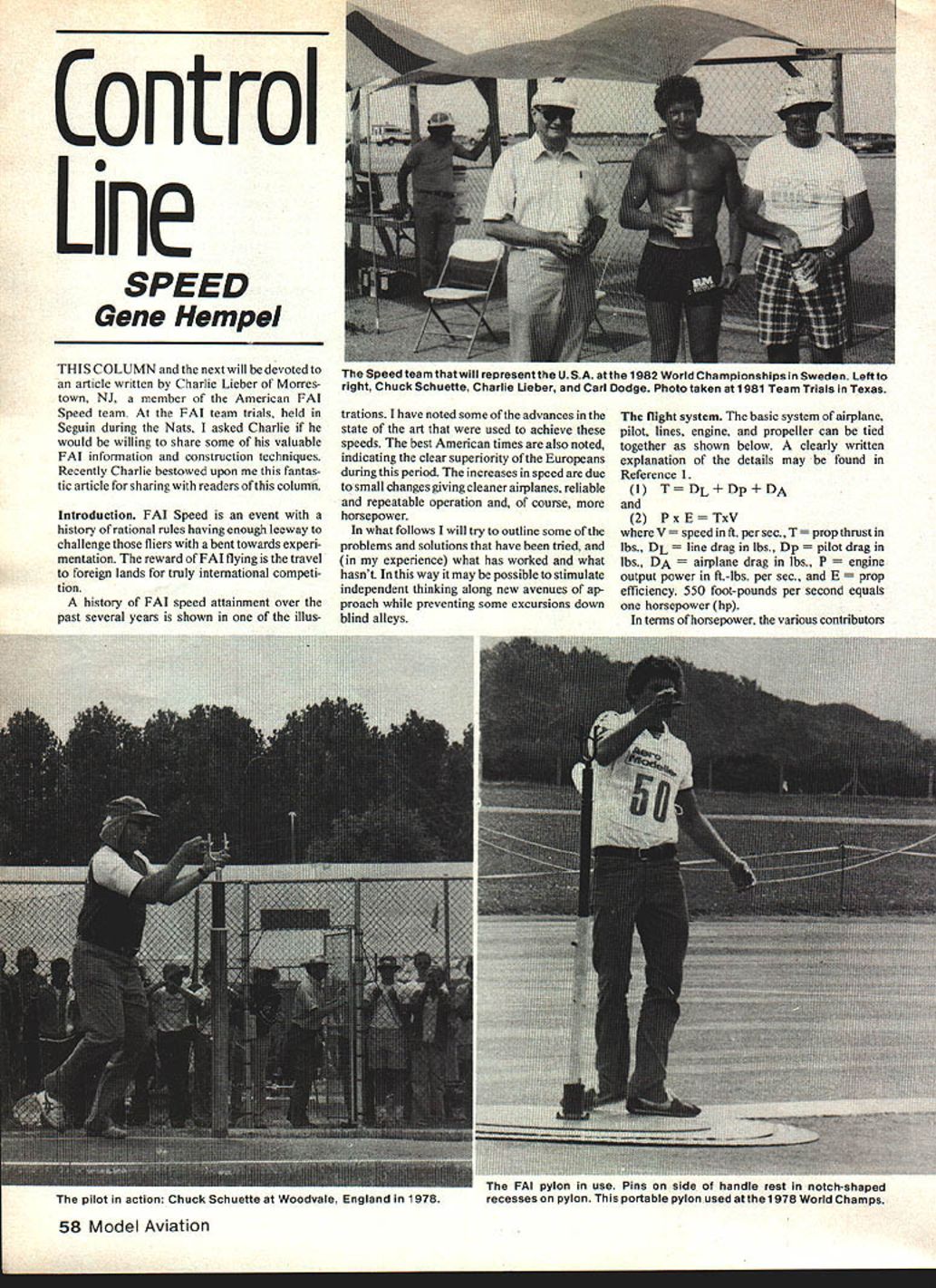
This column and the next will be devoted to an article written by Charlie Lieber of Morristown, NJ, a member of the American FAI Speed team. At the FAI team trials held in Seguin during the Nats, I asked Charlie if he would be willing to share some of his valuable FAI information and construction techniques. Recently Charlie bestowed upon me this fantastic article for sharing with readers of this column.
FAI Speed is an event with a history of rational rules having enough leeway to challenge those fliers with a bent toward experimentation. The reward of FAI flying is the travel to foreign lands for truly international competition.
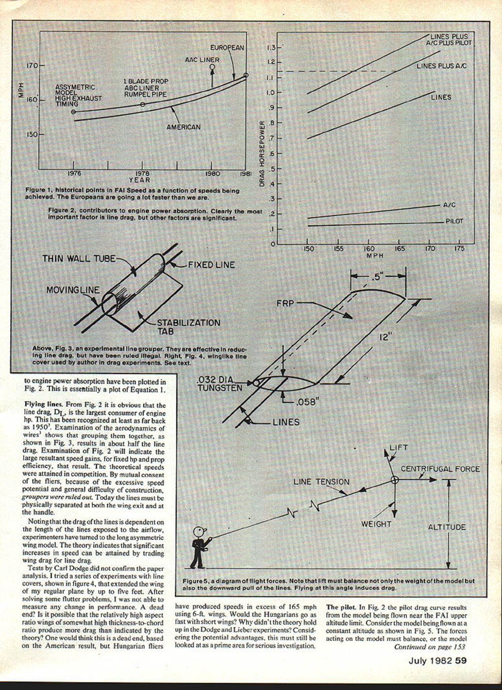
A history of FAI speed attainment over the past several years is shown in one of the illustrations. I have noted some of the advances in the state of the art that were used to achieve these speeds. The best American times are also noted, indicating the clear superiority of the Europeans during this period. The increases in speed are due to small changes giving cleaner airplanes, reliable and repeatable operation and, of course, more horsepower.
In what follows I will try to outline some of the problems and solutions that have been tried, and (in my experience) what has worked and what hasn't. In this way it may be possible to stimulate independent thinking along new avenues of approach while preventing some excursions down blind alleys.
The flight system
The basic system of airplane, pilot, lines, engine, and propeller can be tied together as shown below. A clearly written explanation of the details may be found in Reference 1.
(1) T = D_L + D_p + D_A
and
(2) P × E = T × V
where:
- V = speed in ft/sec
- T = prop thrust in lbs
- D_L = line drag in lbs
- D_p = pilot drag in lbs
- D_A = airplane drag in lbs
- P = engine output power in ft·lbs/sec
- E = prop efficiency
Note: 550 foot-pounds per second equals one horsepower (hp).
In terms of horsepower, the various contributors to engine power absorption have been plotted in Fig. 2. Essentially the plot is of Equation (1).
Flying lines
Fig. 2 shows line drag, D_L, is the largest consumer of engine horsepower. This has been recognized as far back as the 1950s. Examination of the aerodynamics of the wires shows grouping them together (Fig. 3) results in about half the line drag.
Examination of Fig. 2 will indicate large resultant speed gains for fixed hp if prop efficiency can be improved. Theoretical speeds attained in competition caused mutual concern among fliers because excessive speed potential and general difficulty of construction ruled out some designs. Today lines must be physically separated both at the wing exit and at the handle.
Noting that drag of the lines is dependent on the length of line exposed to the airflow, experimenters have turned to long-asymmetric wing models. Theory indicates significant increases in speed can be attained by trading wing drag for line drag. Tests Carl Dodge performed confirmed the paper analysis. He tried a series of experiments with line covers (shown in Fig. 4) and an extended wing on a regular plane up to five feet. After solving some flutter problems he was able to measure the change in performance.
It appeared to be a dead end; relatively high aspect-ratio wings with somewhat high thickness-to-chord ratios produce the drag indicated by theory. One would think this a dead end based on American results, but Hungarian fliers have produced speeds in excess of 165 mph using 6-ft wings. Would Hungarians go fast with short wings? The Dodge–Lieber experiments considered the potential advantages and indicated this must still be looked at as a prime area for serious investigation.
Pilot
Fig. 2 shows a pilot drag curve for a model being flown near the FAI upper altitude limit. Consider a model being flown at constant altitude as shown in Fig. 5. The forces acting on the model must balance; otherwise the model will either move up and down or in and out.
Note that the lift force from the wings must not only balance the weight of the model, but it must also balance part of the line tension acting on the model. In doing this the model generates drag due to lift, called induced drag, and the speed is penalized. Conversely there is some constant flight altitude that allows the lift to go to zero because the line tension balances the model weight.
Using Fig. 5, it has been shown that the distance below the pylon level that the pilot should fly the airplane to minimize drag is:
(3) d = R^2 g / V^2
where:
- d = distance below pylon in ft
- R = 52 ft (line length)
- V = airplane speed in ft/sec
- g = acceleration due to gravity (ft/sec^2)
For example, at 165 mph (242 ft/sec) the distance d is 1.49 ft. The pilot-induced drag at this altitude is zero. At that speed the high flier would be going 157.5 mph.
If at all possible, practice flying exclusively in the FAI pylon style in order to make both steady flight and low flight a natural thing under all weather conditions.
Closing
Thanks, Charlie. That's it for this month, guys. The rest of the article will appear in the next Speed column. Meanwhile, I suggest that you start looking at flying FAI Speed. It is very challenging.
Gene Hempel 301 N. Yale Dr. Garland, TX 75042
Transcribed from original scans by AI. Minor OCR errors may remain.

