
Control Line: SPEED
Gene Hempel
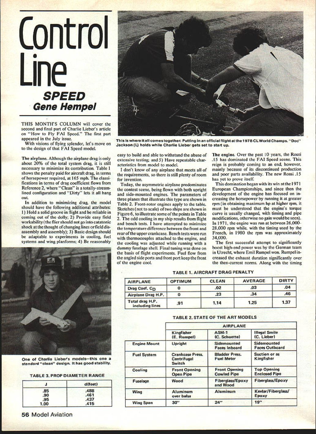
THIS MONTH'S COLUMN will cover the second and final part of Charlie Lieber's article on "How to Fly FAI Speed". The first part appeared in the July issue.
With visions of flying splendor, let's move on to the design of that FAI Speed model.
The airplane
Although the airplane drag is only about 20% of the total system drag, it is still necessary to minimize its contribution. Table 1 shows the penalty paid for aircraft drag, in terms of horsepower required, at 165 mph. The classifications in terms of drag coefficient follow from Reference 2, where "Clean" is a totally-streamlined configuration and "Dirty" lets it all hang out.
In addition to minimizing drag, the model should have the following additional attributes:
- Hold a solid groove in flight and be reliable in coming out of the dolly.
- Provide easy field workability (the flier should not go into catatonic shock at the thought of changing lines or field disassembly and assembly).
- Basic design should be adaptable to experiments in cooling, fuel systems and wing planforms.
- Be reasonably easy to build and able to withstand the abuse of extensive testing.
- Have repeatable characteristics from model to model.
I don't know of any airplane that meets all of the requirements, so there is still plenty of room for invention.
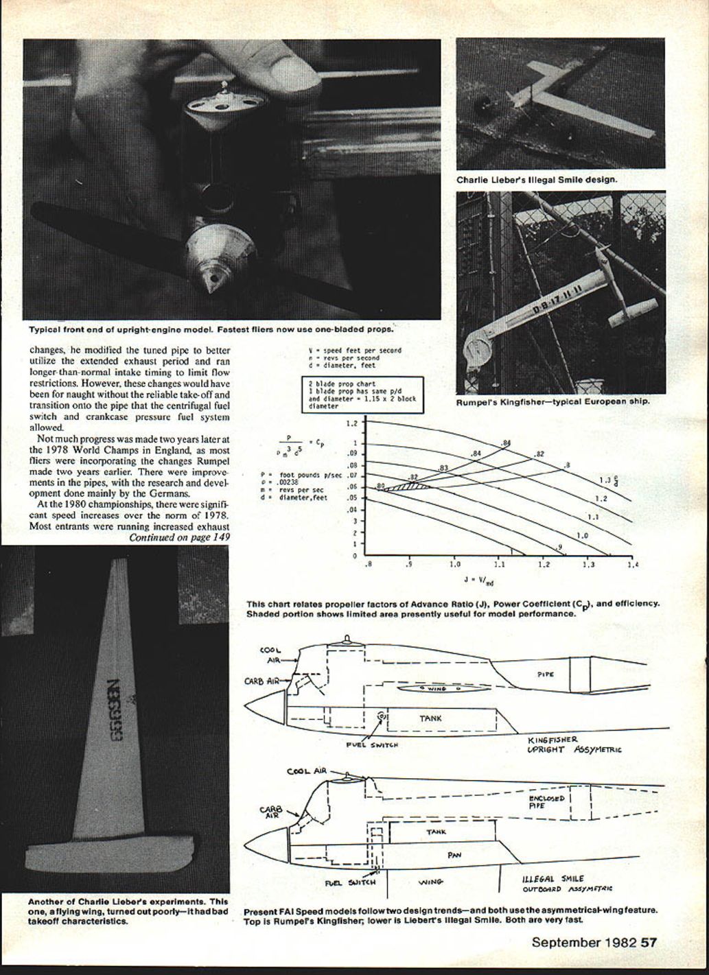
Today, the asymmetric airplane predominates the contest scene, being flown with both upright and side-mounted engines. The parameters of three planes that illustrate this type are shown in Table 2. Front-rotor engines apply to the table. Sketches (not to scale) of two ships are shown in Figure 6 to illustrate some of the points in Table 2.
The odd cooling in my ship results from flight and bench tests. I have attempted to minimize the temperature difference between the front and rear of the upper crankcase. Bench tests were run with thermocouples attached to the engine, and the cooling was adjusted while running with a dummy fuselage shell. Final tuning was done on the basis of flight experiments. Fuel flow from the angled side ports and front port keep the front of the engine cool.
Table 1 — Aircraft Drag Penalty (at 165 mph)
- Columns: Optimum | Clean | Average | Dirty
- Drag Coefficient (CD): 0 | 0.02 | 0.03 | 0.04
- Airplane Drag H.P.: 0 | 0.23 | 0.34 | 0.46
- Total drag H.P. including lines: 0.91 | 1.14 | 1.25 | 1.37
Table 2 — State of the Art Models
- Kingfisher (E. Rumpel)
- Engine Mount: Upright
- Fuel System: Crankcase Pressure; Centrifugal Switch
- Cooling: Front Opening; Open Pipe
- Fuselage: Wood
- Wing: Aluminum over balsa
- Wingspan: 30"
- ASM-1 (C. Schuette)
- Engine Mount: Sidemounted, Faces Inboard
- Fuel System: Bladder Pressure; Fuel Meter
- Cooling: Front Opening; Cowled Pipe
- Fuselage: Fiberglass/Epoxy and Wood
- Wing: Aluminum
- Wingspan: 24"
- Illegal Smile (C. Lieber)
- Engine Mount: Sidemounted, Faces Outboard
- Fuel System: Suction or as Kingfisher
- Cooling: Top Opening; Enclosed Pipe
- Fuselage: Fiberglass/Epoxy
- Wing: Kevlar/Fiberglass/Epoxy
- Wingspan: 19"
Table 3 — Prop Diameter Range
- J = 0.85 → d = 0.488 ft (5.86 in.)
- J = 0.90 → d = 0.461 ft
- J = 0.95 → d = 0.437 ft
- J = 1.00 → d = 0.415 ft
The engine
Over the past 10 years, the Rossi .15 has dominated the FAI Speed scene. This reign is probably coming to an end, however, mainly because of its discontinued production and poor parts availability. The new Rossi .15 has yet to prove itself.
This domination began with its win at the 1971 European Championships, and since then the development of the engine has focused on increasing the horsepower by running it at greater rpm; in obtaining maximum hp at higher rpm, it must be understood that the engine's torque curve is usually changed, with timing and pipe modifications; otherwise no gain would be seen. In 1971, the engine was run at between 26,000–28,000 rpm while, with the timing used by the French, in 1980 the rpm was approximately 34,000.
The first successful attempt to significantly boost high-end power was by the German team in Utrecht, where Emil Rumpel won. Rumpel increased the exhaust duration significantly over the then-current norms. Along with the timing changes, he modified the tuned pipe to better utilize the extended exhaust period and ran longer-than-normal intake timing to limit flow restrictions. However, these changes would have been for naught without the reliable take-off and transition onto the pipe that the centrifugal fuel switch and crankcase-pressure fuel system allowed.
Not much progress was made two years later at the 1978 World Champs in England, as most fliers were incorporating the changes Rumpel made two years earlier. There were improvements in the pipes, with the research and development done mainly by the Germans. At the 1980 championships, there were significant speed increases over the norm of 1978. Most entrants were running increased exhaust duration (more than 188°) as a means to achieving higher hp. The French won the team title with Constant taking first. The French used 188° exhaust duration with an AAC (aluminum/aluminum/chrome) piston and sleeve setup. Not much work had been done with pipes, however, since 1978.
The 1981 Speed scene in Europe, while not having produced the absolute speed that Constant made on his one fast flight in 1980, has produced an increase in the average speed. Parramon of Spain has consistently run over 268 kph (166 mph), which is no small task. He has done a lot of pipe work, as well as more elegant flow studies, and this seems to be an important part of his success.
In comparison, the U.S. performances have on the whole been in a lower league. I was able to run fairly consistently between 266–267 kph at our team trials with relatively standard equipment — 188° exhaust, 138° transfer, ABC piston/sleeve, 1978 German-style pipe at 304 mm, and a lot of fine tuning. For the newcomer, these speeds may seem impossible. They probably won't be obtained when you start, but they are possible with a lot of hard, thoughtful work.
As far as engines go, things are brighter than they've been for the last few years. The new OPS .15 (P&G Metal Products), Rossi .15 (Bill's Miniature Engines), and Nelson .15 (Kustom Krafstmanship) come from a line of truly world-class engines, and they should produce competitive speeds with sufficient work.
In the area of engine development, I feel that more work in the line of that done by Parramon—pipe modification—is very worthwhile, since making up a series of experimental pipes is a lot easier for the average person than building engines. Combining this work with changes in timing (racing motorcycles are using greater than 200° exhaust) gives one the most potentially time-efficient methods of increasing horsepower.
The propeller
On the engine side of the system, we find the prop listed in the Yellow Pages under "efficiency." There are a lot of guidelines for working with props. My recommendation: find out what the fast guys are using and start there. On the theory side, we begin with a definition of prop efficiency:
E = T × V / P = D × V / 550 hp
- P = Engine output power in foot-pounds per second.
- E = Efficiency (less than 1.0).
- T = Prop thrust in pounds, output.
- D = Drag force in pounds.
- V = Model speed in feet per second.
- hp = Engine output horsepower (input to prop).
To aid in solution of the equation above, Figure 7 has been plotted based upon experimental data taken on props of several pitches. The present practice also places the pitch-to-diameter (p/d) ratio of speed props between 0.85 and 1.0. Using these p/d ratios and Figure 7, we find it most likely that state-of-the-art props have about 81% efficiency and a power coefficient (Cp) of 0.06.
To determine a prop size, let us assume a dynamometer measurement has been made on a "super engine," giving peak hp = 1.4 at 35,000 rpm (n = 583 revs/sec.). Using this hp and multiplying by the efficiency, 0.81, enter Figure 2 at 1.134 drag horsepower and find a speed of 165 mph for the perfect pilot. It is interesting to note that the pilot can, for the engine in question, lose the system about 8 mph.
Finally, on Figure 7, note the range of values over which d may vary is limited by J with both speed (V) and engine revs per second (n) now fixed. This spread is shown in Table 3.
Computed from the definition of Cp on Figure 7, this shows that the diameter is 0.488 ft (5.86 in.). Using J = 0.85 and Cp = 0.06 in Figure 7 sets the p/d ratio at 0.92.
Note that the propeller diameter (d) applies to a two-bladed prop. To translate to a one-blader multiply d by a constant, 1.15. This results in a one-blade diameter of 6.7 inches. The p/d ratio is unchanged at 0.92, giving a pitch of 6.1 inches. The dimensions of one of the one-bladers that I used at the 1981 team trials was 6.5-in. diameter by 6-in. pitch. The speed turned was 165 mph!
A better conversion multiplier when going from two-blade to one-blade might be 1.12, in terms of present practice. A detailed design procedure giving information on the chord distribution and pitch distribution is available in Reference 7.
References
- "Analytic and Experimental Tools Useful in Selecting and Developing Power Model Propellers" by D. Monson, NFFS Symposium 1980.
- "Drag of Control Lines and Models" by H. Jex et al., 1951–52 Model Aeronautic Yearbook.
- Hoerner, S., Fluid Dynamic Drag (Interference Drag, Two Circular Cylinders).
- Seely and Ensign, Mechanics — "The Conical Pendulum."
- "Choosing the Best Wakefield Propeller" by R. Meuser, NFFS Symposium 1970.
- "Propellers Made Painless" by D. Mendell, NFFS Symposium 1970.
- "Analytic Design of Propellers Having Minimum Induced Loss" by E. Larrabee, NFFS Symposium 1977.
I hope by the time the readers of this column make an attempt to fly FAI Speed, each one will appreciate the amount of effort that goes into putting together such a constructive article. I hope everyone enjoys the article. Tell 'em you read it in the Model Aviation Speed Column. Once again, thanks to Charlie Lieber for his willingness to share so much information with us.
Gene Hempel 301 North Yale Dr., Garland, TX 75042.
Transcribed from original scans by AI. Minor OCR errors may remain.

