
Control Line: SPEED
Gene Hempel
Many times I have asked for feedback from modelers concerning some type of information for the Speed column. This month (and to be continued in the next column), I want to share with you a letter from Mr. Jerry Rautio. He has spent an enormous amount of time drafting his letter; he is a retired plant engineer from General Electric and has developed an interest in propulsion systems for models. His subject will be propeller design and matching engine power and the propeller.
The reference book for Mr. Rautio's article is Aircraft Propeller Design by Fred Weick.
Letter from Jerry Rautio
I am writing to thank you for publishing two of the most interesting magazine columns in recent memory: specifically Charlie Lieber's "How to Fly FAI Speed," in the July and September 1982 issues of Model Aviation! I say this despite the fact that I am not a CL flier. It's because I do appreciate the logical approach you've taken to designing a winning Speed airplane.
My interest is in the design of propulsion systems for competition models, especially Formula 1 pylon racers, so for my own satisfaction I have made a "comparative study" of an FAI CL Speed airplane, using my own methods of design. I thought you might find something of interest in this study and am taking the liberty of enclosing my work with this letter.
I was pleasantly surprised to calculate a thrust hp required (you called it drag hp) of 1.230, as compared to your 1.134. I attribute the difference between the two to the difficulty of calculating the exact drag variation due to skewing of the two control lines. This is my "r-factor." If the rules permitted a line spacing of 1 diameter, parallel to flight, this r-factor would be 0.4! My method of calculating line THP is not as elegant as the calculus, but it does give a clear picture of where line drag has to be reduced.
Your article assumed an engine output of 1.4 bhp at 35,000 rpm at 165 mph. I calculated (further on) that this power would be insufficient! You assumed a propeller efficiency of 81%. This would only be true at very low tip speeds, a condition we do not have. High tip speeds have a devastating effect on efficiency and power requirement.
The data necessary for designing the propeller are:
- the thrust horsepower required,
- the rated maximum bhp and rpm of the engine,
- the speed of the model,
- the relative air density.
We are designing for a speed of 165 mph (or 170 mph), have found the thrust hp required, and assume a standard, sea-level air density. How can we obtain the vital engine information? The only way is by testing the engine/pipe assembly on a torque stand as outlined in the articles "The Whatley Torque Stand," Sport Aviation January 1983, and Clarence Lees' "Engine Clinic," RCM June 1981. A strobe would be required for accurate rev-counting.
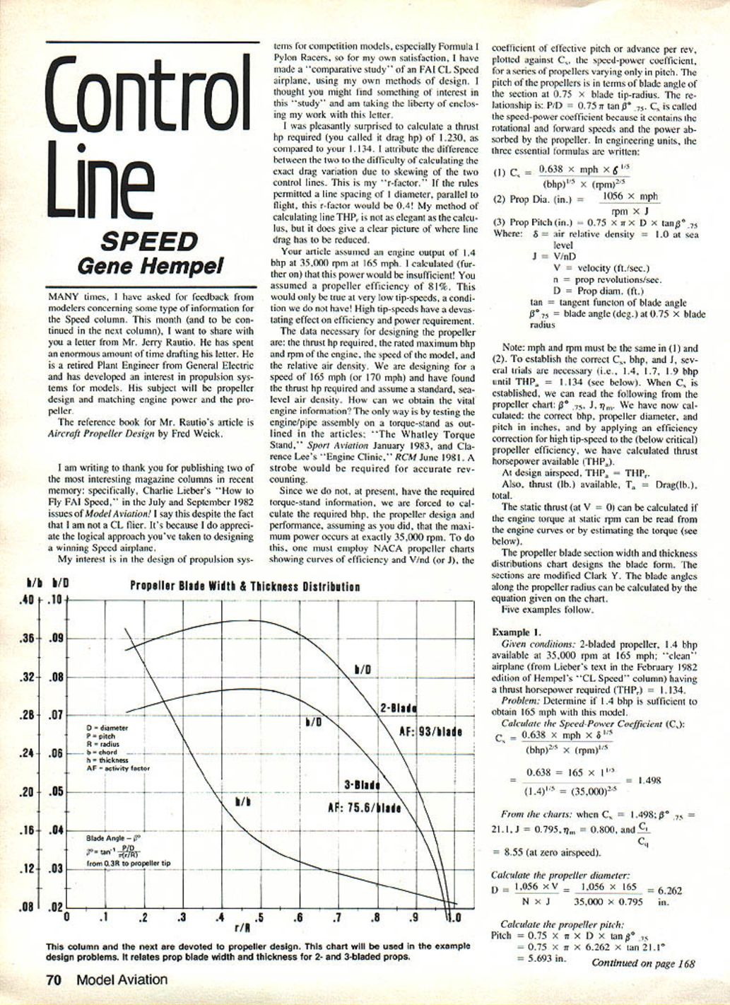
Since we do not, at present, have the required torque-stand information, we are forced to calculate the required bhp, the propeller design and performance, assuming as you did that the maximum power occurs at exactly 35,000 rpm. To do this, one must employ NACA propeller charts showing curves of efficiency and V/nd (or J), the coefficient of effective pitch or advance per rev, plotted against C_p, the speed-power coefficient, for a series of propellers varying only in pitch. The pitch of the propellers is in terms of blade angle of the section at 0.75 × blade tip-radius. The relationship is P/D = 0.75 × tan β*, where β* is the blade angle at 0.75R. C_p is called the speed-power coefficient because it contains the rotational and forward speeds and the power absorbed by the propeller.
Essential formulas (engineering units)
- C_p = 0.638 × mph × δ^(1/5) / [ (bhp)^(2/5) × (rpm)^(3/5) ]
- Propeller diameter (in) = 1056 × mph / (rpm × J)
- Propeller pitch (in) = 0.75 × π × D × tan β*
Where:
- δ = air relative density = 1.0 at sea level
- J = V / (nD)
- V = velocity (ft/sec)
- n = prop revolutions/sec
- D = prop diameter (ft)
- tan = tangent function of blade angle
- β* = blade angle (deg) at 0.75 × blade radius
Note: mph and rpm must be consistent when used in (1) and (2). To establish the correct C_p, bhp, and J, several trials are necessary (for example, try 1.4, 1.7, 1.9 bhp until THP_a = THP_r). When C_p is established, we can read β*, η, J, C_t from the propeller chart. We then calculate the correct bhp, propeller diameter, and pitch in inches, and by applying an efficiency correction for high tip speed to the (below-critical) propeller efficiency, we calculate thrust horsepower available (THP_a).
At design airspeed:
- THP_a = THP required
- Thrust available T_a (lb) = total Drag (lb)
The static thrust (at V = 0) can be calculated if the engine torque at static rpm can be read from the engine curves or by estimating the torque. The propeller blade section width and thickness distribution chart designs the blade form; the sections are modified Clark Y. Blade angles along the propeller radius can be calculated by the equation given on the chart.
Examples
#### Example 1 Given conditions:
- 2-bladed propeller
- 1.4 bhp available at 35,000 rpm
- 165 mph
- "Clean" airplane (from Lieber's text) having a thrust horsepower required THP_r = 1.134
Problem: Determine if 1.4 bhp is sufficient to obtain 165 mph with this model.
Calculate the Speed-Power Coefficient (C_p): C_p = 0.638 × 165 × 1^(1/5) / [ (1.4)^(2/5) × (35,000)^(3/5) ] = 1.498
From the charts:
- β* = 21.1°
- J = 0.795
- η = 0.800
- C_t = 8.55 (at zero airspeed)
Calculate the propeller diameter: D = 1056 × 165 / (35,000 × 0.795) = 6.262 in.
Calculate the propeller pitch: Pitch = 0.75 × π × 6.262 × tan 21.1° = 5.693 in.
Thrust available:
- T_a = THP_a × 375 / mph
- Using THP_a = 0.850 hp: T_a = 0.850 × 375 / 165 = 1.932 lb at 165 mph.
Conclusion: Power is insufficient for 165 mph, even for Lieber's "clean" system, which had a calculated THP_r = 0.91.
#### Example 2 Given conditions:
- 3-bladed propeller
- THP required = 1.134 at 165 mph
- 35,000 rpm
Problem: Calculate engine bhp required, and design propeller to furnish the required thrust horsepower for these conditions.
Calculate the Speed-Power Coefficient: C_p = 0.638 × 165 × 1^(1/5) / [ (1.9 × 0.7)^(1/5) × (35,000)^(3/5) ] = 1.573
From the charts:
- β* = 21.3°
- J = 0.807
- η_m = 0.776
- C_t = 8.45 (at zero airspeed)
Calculate the propeller diameter: D = 1056 × 165 / (35,000 × 0.807) = 6.169 in. (3-blade)
Calculate the propeller pitch: Pitch = 0.75 × π × 6.169 × tan 21.3° = 5.667 in.
Pitch-to-diameter ratio (P/D) = 0.918
Prop tip speed: tip speed = sqrt[(1.467 V)^2 + (π D N / 60)^2] = 973 ft/sec
K = efficiency correction for tip speed = 0.770 η = propulsive efficiency at maximum speed = K × η_m = 0.770 × 0.776 = 0.5975
Thrust horsepower available: THP_a = BHP × η = 1.9 × 0.5975 = 1.135 at 165 mph
Note: Q is the estimated static-rpm torque. For real design work, read the exact torque from the bhp/torque curve for an actual engine.
Conclusion: Engine must produce 1.9 bhp at 35,000 rpm at an airspeed of 165 mph. The prop is 3-bladed, diameter 6.169 in., pitch 5.667 in. The pitch at the 0.75R point must be 21.3°, and the airfoil is modified Clark Y. Blade activity factor = 75.6. P/D = 0.918.
#### Examples 3–5 (summary)
- Example 3: 2-bladed prop at 35,000 rpm delivering THP = 1.134 at 165 mph required an available engine bhp of 2.1. Calculated prop: D = 6.895 in., pitch = 5.865 in. Tip speed = 1,080 ft/sec, K = 0.687, propulsive efficiency ≈ 0.540. Horsepower required increases due to high tip speed.
- Example 4: 3-bladed prop at 35,000 rpm delivering THP = 1.230 (value used by Lieber for an "average" model) resulted in required bhp ≈ 2.1. Prop diameter = 6.301 in., pitch = 5.599 in. Prop tip speed = 818 ft/sec; propulsive efficiency was greater than in Example 3.
- Example 5: 2-bladed prop under the same rpm, airspeed, and THP (1.230) gave D = 7.091 in., pitch = 5.801 in. Tip speed = 973 ft/sec, K = 0.770, overall propulsive efficiency ≈ 0.599. Required engine power to deliver THP_r = 1.23 was about 2.06 bhp.
Speed was increased again because of the increased diameter; therefore, propulsive efficiency decreased again, resulting in the need for an engine power output of about 2.39 bhp in some cases. It is very doubtful we could ever get this kind of performance out of a .15 cu. in. engine.
What we're really trying to show here is the interrelation between the number of blades on the prop and the amount of thrust we're trying to get at constant values of rpm and airspeed. Note that our chief enemy is high prop tip speed — propulsive efficiency drops substantially as tip speeds approach about 1,000 ft/sec. Also evident is the fact that we've got to have a clean model to have any hope of getting our high speeds with the power available from a .15.
This discussion will be continued in the next column.
Gene Hempel 301 N. Yale Dr., Garland, TX 75042
Transcribed from original scans by AI. Minor OCR errors may remain.

