
Control Line: Speed
Gene Hempel
This month concludes Jerry Rautio's propeller discussion begun in the May issue. I want to thank Jerry for sharing his thoughts and ideas about propeller design with us.
The invitation is extended to all who read this CL Speed column to express their opinions and ideas and to share helpful construction techniques.
(Continuing from the May issue.)
Two additional examples were calculated, this time for an airspeed of 170 mph (the other five examples were all for 165 mph).
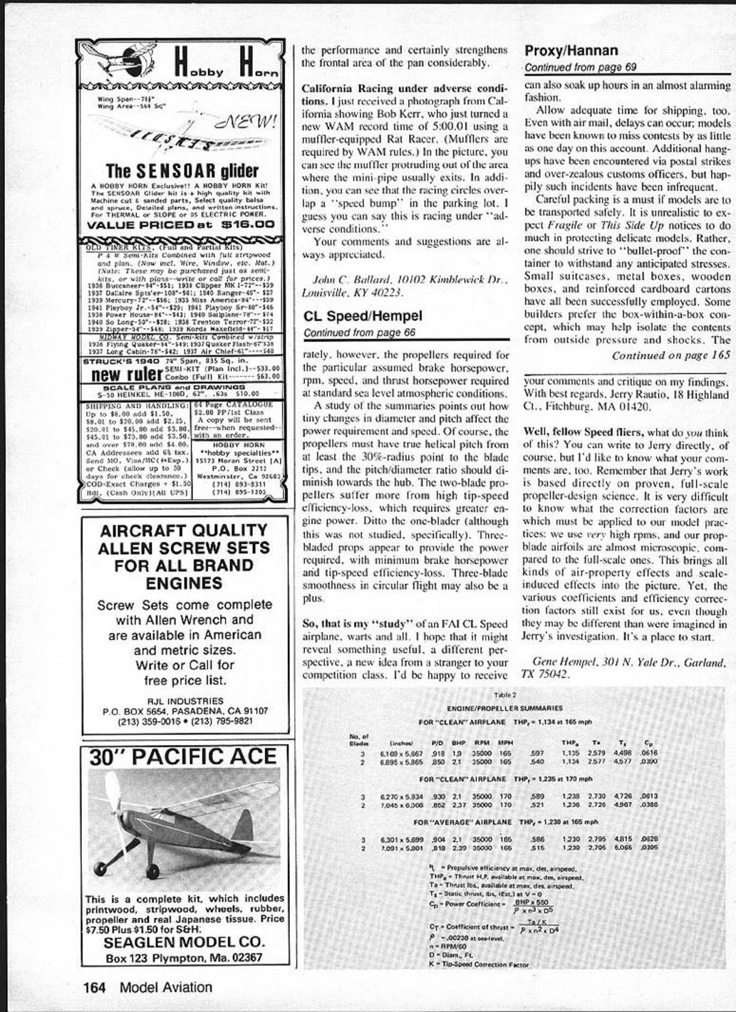
- In the sixth example, a three-bladed propeller was designed to give 170 mph with the engine turning 35,000 rpm and delivering enough brake horsepower to give 1.235 thrust horsepower. (Examples of the equations used and the calculations involved were in the May issue.) The conclusion was that the engine would have to produce 2.1 brake horsepower, and the propeller would have a diameter of 6.27 in. and a pitch of 5.834 in. Prop tip speed was 989 ft./sec., giving an efficiency correction factor for tip speed of 0.758. Overall propulsive efficiency was 0.5899 (59%).
- The seventh example was for a two-bladed prop at the same airspeed, rpm, and thrust horsepower required. The conclusion was that the engine would have to produce 2.37 brake horsepower, and the propeller would have a diameter of 7.045 in. and a pitch of 6.008 in. Prop tip speed was 1,104 ft./sec., resulting in an efficiency correction factor of 0.6628 and an overall propulsive efficiency of 0.5216 (52%).
To sum up the theoretical propulsion unit requirements: we must hope to get an engine power output of 1.9 to 2.1 brake horsepower at 35,000 rpm. If we can get it, then a three-bladed propeller with a diameter of 6.169 to 6.301 in. would be desirable. If a two-bladed prop were to be used, its maximum diameter should be 6.895 in. A three-blader is actually more efficient, and will probably be considerably smoother in circular flight. The results of six of the examples calculated in this exercise are summarized in one of the tables.
Without the exact brake horsepower/rpm and torque/rpm curves for our engine/tuned-pipe assembly, no guarantee can be given that these calculations have given us the absolute delineation of the propeller we are searching for. They represent quite accurate estimates of the propellers required for the particular assumed brake horsepower, rpm, speed, and thrust at standard sea level atmospheric conditions.
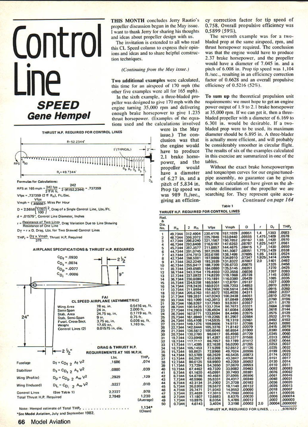
Thrust H.P. required for control lines
Formulas for calculations:
- RPS at 165 mph = 242 rps = 242/(2π(52.2344)) = .737359 (2πR) ft./sec.
- Vfps = .737359 (2π R) n, ft./sec.
- Vfps = Vmph × 1.466667 (miles per hour to feet per second)
- D = .2566 (u/mph)^2 / 100 — Drag of a single control line, lbs./ft.
- d = .01575" — Control line diameter, inches
- r = Resistance ratio of two lines (drag variation due to line skewing / resistance of one line)
- DT = r × D — Drag, lbs. for two skewed control lines
- THP = DT × Vmph / 375 — Thrust H.P. required
Airplane specifications & thrust H.P. required
Coefficients:
- C_Df = 0.0930
- C_Ds = 0.0074
- C_Dp = 0.0077
- C_Di = 0.0006
CL Speed Airplane (asymmetric)
- Wing area: 78 sq. in. = 0.5416 sq. ft.
- Semi-span: 24 in. = 2.000 ft.
- Stabilizer area: 24.75 sq. in. = 0.1719 sq. ft.
- Stabilizer semi-span: 9 in. = 0.75 ft.
- Fuselage cross-sectional area: 3.75 sq. in. = 0.026 sq. ft.
- Weight: 17.65 oz. = 1.103 lb.
- Control lines (2): 0.01575 in. dia.
Drag & Thrust H.P. requirements at 165 mph
- Fuselage
- Df = Cd_f × 1/2 Af V^2 = 0.1686 lbs — THP 0.074
- Stabilizer
- Ds = Cd_s × 1/2 As V^2 = 0.0880 lbs — THP 0.039
- Wing (profile)
- Dp = Cd_p × 1/2 Aw V^2 = 0.2929 lbs — THP 0.129
- Wing (induced)
- Di = Cd_i × 1/2 Aw V^2 = 0.0227 lbs — THP 0.010
- Control lines (see Table 1)
- D = 2.2227 lbs — THP 0.978
Total drag = 2.7949 lbs — Total thrust H.P. required = 1.230 (average)
Note: Hempel estimate of total THP_r = 1.134* (clean) *See Model Aviation, July and September 1982.
A study of the summaries points out how tiny changes in diameter and pitch affect the power requirement and speed. Of course, the propellers must have true helical pitch from at least the 30%-radius point to the blade tips, and the pitch/diameter ratio should diminish towards the hub. The two-blade propellers suffer more from high tip-speed efficiency loss, which requires greater engine power. Ditto the one-blader (although this was not studied specifically). Three-bladed props appear to provide the power required, with minimum brake-horsepower and tip-speed efficiency loss. Three-blade smoothness in circular flight may also be a plus.
So, that is my study of an FAI CL Speed airplane, warts and all. I hope that it might reveal something useful, a different perspective, a new idea from a stranger to your competition class. I'd be happy to receive your comments and critique on my findings.
With best regards, Jerry Rautio 18 Highland Ct., Fitchburg, MA 01420
Well, fellow speed fliers, what do you think of this? You can write to Jerry directly, of course, but I'd like to know what your comments are, too. Remember that Jerry's work is based directly on proven, full-scale propeller-design science. It is very difficult to know what the correction factors are which must be applied to our model practices: we use very high rpms, and our prop-blade airfoils are almost microscopic compared to the full-scale ones. This brings all kinds of air-property effects and scale-induced effects into the picture. Yet, the various coefficients and efficiency correction factors still exist for us, even though they may be different than were imagined in Jerry's investigation. It's a place to start.
Gene Hempel 301 N. Yale Dr., Garland, TX 75042
Table 2
ENGINE/PROPELLER SUMMARIES
Transcribed from original scans by AI. Minor OCR errors may remain.

