
Control Line: Speed
Phill Bussell
Formula 40 Speed a Natural
Airframe Design: Let's quickly review the rules applicable to the design of the airframe. We have no wing loading or power loading or cross sectional requirements to contend with. Our model shall have a fixed landing gear with a minimum of one wheel and no single-line control systems are allowed. That's all! A word to the wise, Rat Fliers, the 1975 National Speed Director was very lenient in regard to using rat lines in Formula 40 Speed. This was great because at that time Formula 40 Speed was a provisional event — in 1976 this is not the case. The 1976 Event Director may take a dim view on lengthening short lines with line connectors, even if they are of the safe variety.
We have digested AMA's rules governing our design, now let's consider Phill and Dub's rules. Our "rules" have been established through 24 years of competition Speed Flying.
Light but Strong: If we are going to win, our model must be light. If we are going to be safe and, if our model is to stay together, it must be strong. A light but strong airframe should weigh no more than 26 ounces and should last three or four flying seasons. If you are careful in your wood selection, construction and finishing techniques, I am sure you can hold the weight of your finished model to less than 24 ounces. (This includes an engine and pan.)
Balance: To fly properly, our model must balance properly. If it is tail-heavy, it will not groove. If it is nose heavy, it will pull hard and obviously go slower. Theoretically, we want our airframe to be light on the flying lines, yet groove in both calm and windy weather. Our balance point (center of gravity) of our airframe should be exactly where the flying lines come out of our wing tip. Also, bring your lines out of your wing tip as close together as possible and no further back than the high point of your airfoil. If your model is balanced properly you should be able to hang your model from the flying lines and the nose should not hang down nor should the tail hang down. Again, if the nose of your model hangs down (outside of circle), it will pull excessively hard. If the tail hangs down, your model will not groove properly and it will be hard to fly. A properly grooving model will always outrun an erratic flying model for obvious reasons.
Wings. Airfoils. High Point. Taper. Leading Edge: Let's establish one thing right now; no matter how fast we go, our airframes are still considered to be low speed (by comparison). Low speed airframes operate better with low speed airfoils and blunt leading edges are an integral part of low speed airfoils. We have found through experience that a symmetrical airfoil with a blunt leading edge works very well. Flat bottom airfoils tend to rise coming into the wind and fall downwind on the downwind side of the circle. This makes the model hard to groove, especially in windy weather. On some of our smaller models — 1/2 A and sometimes B — we will use a lifting airfoil, never more than 1/2 lifting at the root and symmetrical at the tip. This tends to cut down the angle of attack our model must fly at to create enough lift to support the aircraft. But in all honesty, I can't tell the difference in flying characteristics of models with a lifting section as opposed to those with a symmetrical section.
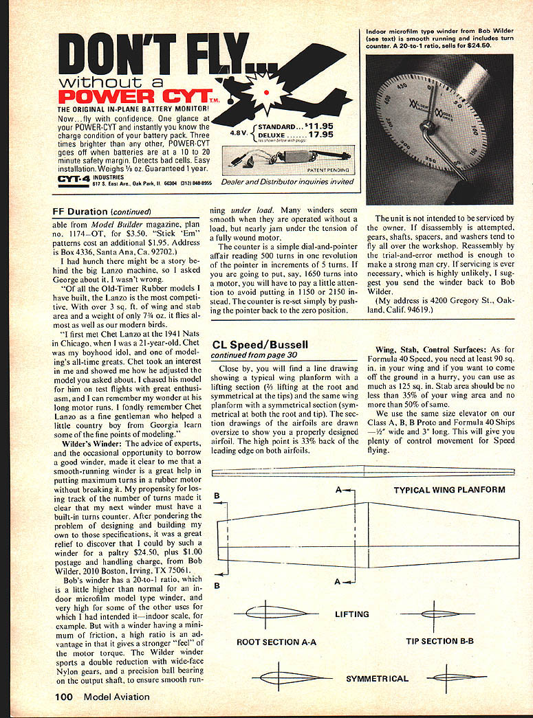
The high point of the airfoil should be somewhere between 25% and 35% of the chord back from the leading edge, but it is not critical. From an aesthetic point of view, we like to taper our wings (airfoil section at the tip is thinner than at the root), but this is not necessary to go fast. Blunt leading edges are faster than sharp leading edges for many reasons, one of which is that a blunt leading edge is not as critical to control correction and this is important if you want your model to groove. Close by, you will find a line drawing showing a typical wing planform with a lifting section (3/8 lifting at the root and symmetrical at the tip) and the same wing planform with a symmetrical section (symmetrical at both the root and tip). The section drawings of the airfoils are drawn oversize to show you a properly designed airfoil. The high point is 33% back of the leading edge on both airfoils.
Wing, Stab, Control Surfaces: As for Formula 40 Speed, you need at least 90 sq. in. in your wing and if you want to come off the ground in a hurry, you can use as much as 125 sq. in. Stab area should be no less than 35% of your wing area and no more than 50% of same.
We use the same size elevator on our Class A, B, Proto and Formula 40 Ships — 1/2" wide and 3" long. This will give you plenty of control movement for Speed flying.
Control System — Horn Length, Bell‑crank Length, Crank Arm Length, Line Spacing at Handle
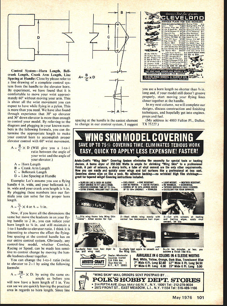
Close by, please refer to a line drawing of a complete control system from the handle to the elevator horn. By experiment, we have found that it is comfortable to move your wrist approximately 60° without moving your arm. This is about all the wrist movement you can expect to have while flying in a pylon. This is more than you need. We have also found through experience that 30° up elevator and 30° down elevator is more than enough to control your model. By referring to the diagram and plugging in your known numbers in the following formula, you can determine the appropriate length to make your control horn to accomplish proper elevator control with 60° wrist movement.
A = B / C × D (Will give you a 1‑to‑1 ratio between the angle of your wrist and the angle of your elevator.)
A = Horn Length B = Crank Arm Length C = Bellcrank Length D = Line Spacing at Handle
Example: Let’s assume you use a flying handle 4 in. wide, and your bellcrank is 2 in. wide and your crank arm length is 1/4 in. By plugging these numbers into our formula you can solve for the proper horn length.
A = 1/2 × 4 or A = 1/2 in.
Now, if you leave all the dimensions the same but move the leadouts in on your flying handle to 2 in., you can reduce your horn length to 1/4 in., and still maintain a 1‑to‑1 handle‑to‑elevator ratio. I think it is interesting to observe the effect the flying‑line spacing at the control handle has on our entire control system. Obviously, any control‑line model, whether Combat, Racing or Speed, can be made less sensitive to control change by moving the handle leadouts closer together.
You can change the 1‑to‑1 ratio (wrist to elevator) to 2‑to‑1 by using the following formula:
A = 2B / C × D; by using the same example as before you will now have a horn length of 1 in. You can see we are quickly leaving the practical area in regards to horn length. Since line spacing at the handle is the easiest element to change in our control system, I suggest you use a horn length no shorter than 3/8 in. long and if your model still doesn’t groove properly, start moving your flying lines closer together at the handle.
In my next column, we will complete our designs, discuss construction and finishing techniques, and hopefully get into engines, props and fuel.
(My address is: 4803 Fallon Pl., Dallas, TX 75227.)
Transcribed from original scans by AI. Minor OCR errors may remain.

