
Control Line
SPEED — Gene Hempel
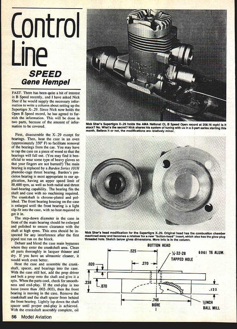
FAST. There has been quite a bit of interest in B Speed recently, and I asked Nick Sher if he would supply the necessary information to write a column about setting up the Supertigre X-29. Since Nick now holds the Open B Speed record, he agreed to furnish the information. This will be done in two parts because of the amount of information to be covered.
Case and Bearing Work
- Disassemble the X-29 except for the bearings.
- Heat the case in an oven (approximately 350°F) to facilitate removal of the bearings from the case. You may have to rap the case on a piece of wood so that the bearings will fall out. Wear heavy gloves to protect your fingers from burns.
- Replace the main bearing with a Barden Series 101H phenolic-cage thrust bearing. Barden's precision bearing is appropriate for this application, with an upper speed limit of 88,600 rpm and both radial and thrust load-bearing capability. The bearing fits the shaft and case with no machining required.
- The crankshaft is chrome-plated and polished. Enlarge the front bearing housing in the case until the front bearing is a light slip-fit; no heat should be required to insert it.
- Enlarge and polish the step-down diameter in the case in front of the main bearing to ensure clearance with the shaft at high rpms. Inspect this area for any interference after the first piped test run on the block.
- Deburr and blend the case main bypasses where they enter the crankshaft area.
- Clean all parts thoroughly in lacquer thinner and dry. If available, use an ultrasonic cleaner.
Crankshaft Assembly and End-Play
- Heat the case and assemble the crankshaft, spacer, and bearings into the case.
- With the case still hot, add the prop driver and bolt a prop onto the shaft; give it a spin.
- When parts cool, check for smoothness and end-play. If end-play is too loose (more than .002–.003 in.), the front bearing is moving in the case. Remove the crankshaft and the shaft spacer from behind the front bearing. Lightly lap down the shaft spacer until proper end-play is achieved.
- With the crankshaft assembly complete, oil liberally and set aside.
Backplate and Rotor
- Remove the rotor backplate and carefully examine it for metal flashing around the edges. Use an X-Acto knife (No. 11 blade) to remove flashing from the face edges.
- Obtain a piece of tempered glass about 12–14 in. square to use as a lapping plate. Place No. 600 grit wet-or-dry sandpaper on the glass and pour a small amount of 3-in-1 oil on the sandpaper.
- Sand the face of the backplate in a circular motion until the running surface is smooth (it will have a gray appearance after sanding). Clean the backplate with liquid soap and water, then dip in lacquer thinner and allow to dry thoroughly.
- Rotor timing should be: Open 35° ABDC, Close 65° ATDC. Mark timing by painting layout ink on the back surface and scribing lines through the venturi opening with the proper degree-wheel setting.
- Mill rotor dimensions: round sharp corners except timing openings (which should be deburred). Balance the rotor and finally chrome-plate it. Polish both the retaining pin and the rotor-mounting hole so the rotor spins freely on its pin.
- Reassemble backplate and rotor, placing two strips of .006-inch feeler gauge material between rotor and backplate. Press the rotor pin against the rotor until you have a snug fit, then tighten the rotor-pin set screw. Use Loctite on the retaining screw. Apply silicone bathtub sealer on the rear backplate where the rotor pin terminates.
Sleeve and Piston Rework
- Sleeve/piston rework requires access to a lathe. The stock sleeve and piston are relatively soft; replace the piston with one machined from hard silicon aluminum.
- Piston blanks are obtained from Performance Model Parts; blanks are machined by Precision Metal Grinding. (Addresses will be given in the next column.)
- The stock sleeve should be rechromed and honed; the sleeve is finished with a .003 in. taper.
- Skirts of sleeve/piston are relieved to facilitate better breathing.
- After cylinder ports are cut and deburred, align the piston at the bottom of its stroke and scribe the relief-port outlines. Remove piston material with a hand-held rotary cutting tool, then finish with careful file work and emery paper. Replace the piston and check that piston clearance around the liner is .002–.003 in.
Cylinder Timing and Porting
- Cylinder timing:
- Exhaust: 176° open ATDC
- Intake: 130°–133° open ATDC
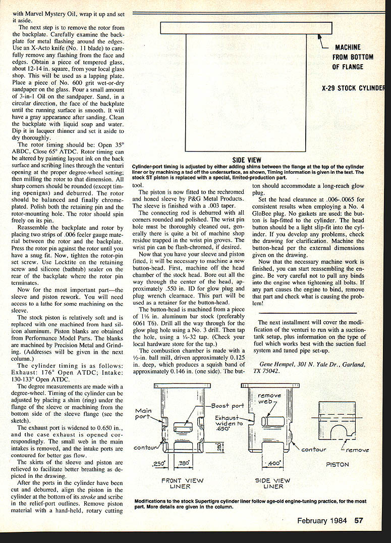
- Degree measurements are made with a degree-wheel. Timing of the cylinder can be adjusted by placing a shim ring under the flange of the sleeve or by machining the bottom side of the sleeve flange.
- Porting changes:
- Widen the exhaust port by .065 in.; open the case exhaust correspondingly.
- Remove the small web at the main intakes.
- Contour intake ports for better gas flow.
Connecting Rod and Wrist Pin
- Deburr and round all corners of the connecting rod and polish.
- Thoroughly clean the wrist pin hole; machine-shop residue is often trapped in the wrist-pin grooves.
- The wrist pin may be flash-chromed if desired.
Button-Head (Head) Modification
- Machine off the head chamber of the stock head and bore all the way through the center of the head to approximately .550 in. I.D. for glow-plug and plug-wrench clearance. This part will be used as a retainer for the button-head.
- Machine the button-head from 1½-in. aluminum bar stock (preferably 6061-T6). Drill all the way through for the glow-plug hole using a No. 3 drill, then tap the hole with a 4-32 tap.
- Machine the combustion chamber with a ½-in. ball mill driven approximately 0.125 in. deep, producing a squash band of approximately 0.146 in. (one side). The button should accommodate a long-reach glow plug.
- Set the head clearance at .006–.0065 in. for consistent results when employing a No. 4 glow plug. No gaskets are used; the button is lap-fitted to the cylinder and should be a light slip-fit into the cylinder.
- Machine the button-head per the external dimensions given on the drawing.
Reassembly and Final Notes
- Reassemble the engine carefully. Do not pull any binds into the engine when tightening bolts. If any part causes the engine to bind, remove that part and check the cause of the problem.
- The next installment will cover modification of the venturi to run with a suction-tank setup, plus information on the type of fuel that works best with the suction fuel system and tuned-pipe setup.
Gene Hempel 301 N. Yale Dr., Garland, TX 75042.
Transcribed from original scans by AI. Minor OCR errors may remain.

