
Control Line: Speed
Gene Hempel
GO FAST (Part II)
This column continues the one in the February 1984 issue. Nick Sher is describing the rework needed to set up the Supertigre X-29 for suction fuel feed. I hope, by the time you read this, all the previously described engine rework is finished.
Engine modifications (continued)
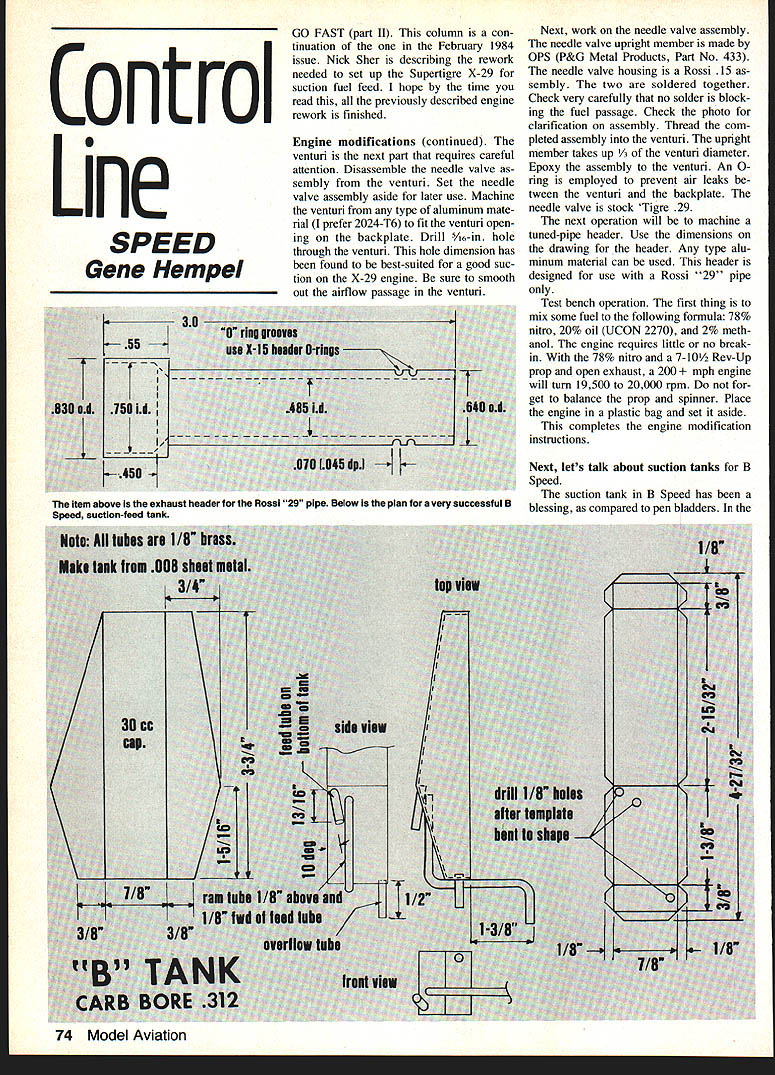
The venturi is the next part that requires careful attention. Disassemble the needle valve assembly from the venturi and set the needle valve assembly aside for later use. Machine the venturi from any type of aluminum material (I prefer 2024-T6) to fit the venturi opening on the backplate. Drill a 5/16-in. hole through the venturi — this hole dimension has been found to be best-suited for a good suction on the X-29 engine. Be sure to smooth out the airflow passage in the venturi.
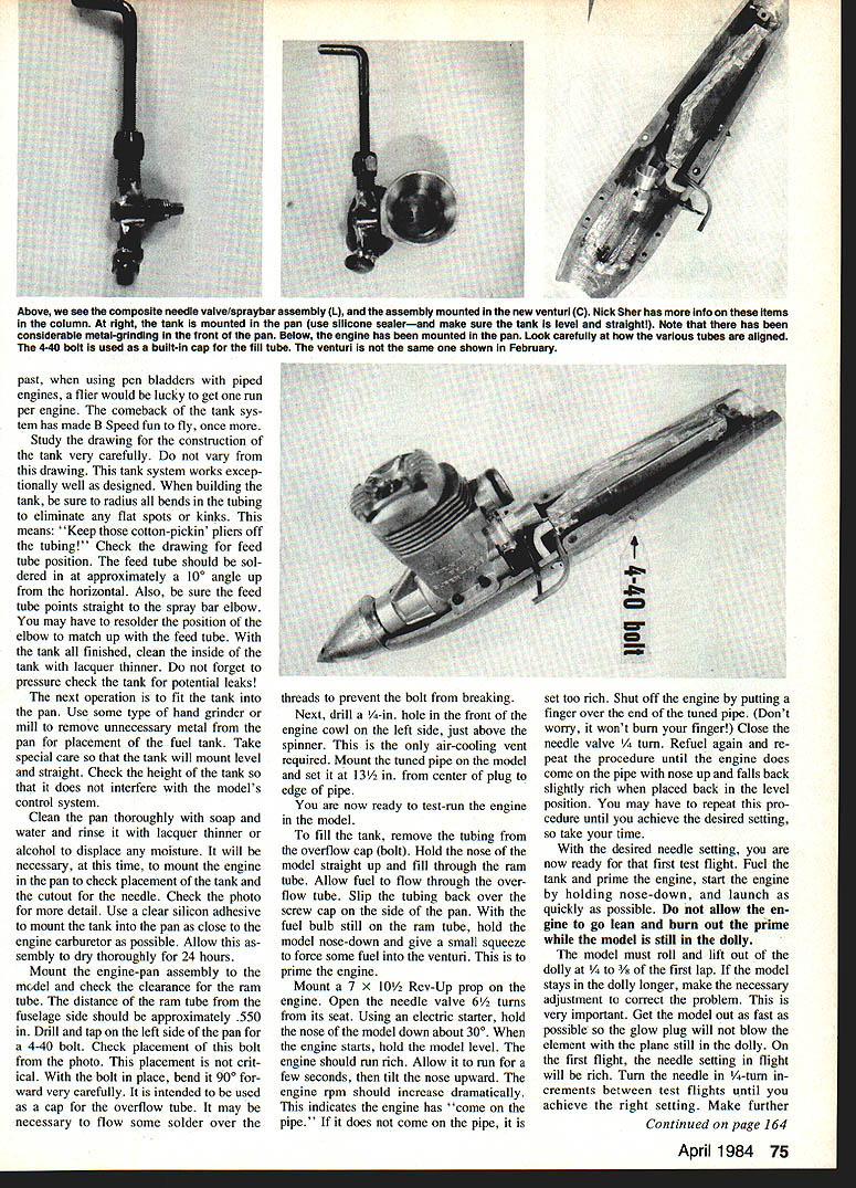
Next, work on the needle valve assembly. The needle valve upright member is made by OPS (P&G Metal Products, Part No. 433). The needle valve housing is a Rossi .15 assembly. The two are soldered together. Check very carefully that no solder is blocking the fuel passage. Thread the completed assembly into the venturi. The upright member occupies approximately one-third of the venturi diameter. Epoxy the assembly to the venturi. Use an O-ring to prevent air leaks between the venturi and the backplate. The needle valve is a stock Tigre .29.
The next operation is to machine a tuned-pipe header. Use the dimensions on the drawing for the header; any aluminum material may be used (I prefer 2024-T6). This header is designed for use with a Rossi "29" pipe only.
Test bench operation
Mix fuel to the following formula: 78% nitro, 20% oil (UCON 2270), and 2% methanol. The engine requires little or no break-in. With the 78% nitro and a 7 x 10½ Rev-Up prop and open exhaust, a 200+ mph engine will turn 19,500 to 20,000 rpm. Do not forget to balance the prop and spinner. Place the engine in a plastic bag and set it aside. This completes the engine modification instructions.
Suction tanks for B Speed
The suction tank in B Speed has been a blessing compared to pen bladders. In the past, using pen bladders piped to engines, the flier would be lucky to get one run per engine. The comeback tank system has made B Speed fun to fly.
Study the drawing of the construction tank very carefully. The tank system works exceptionally well when the builder follows the design. When building the tank, be sure to radius bends in the tubing to eliminate flat spots and kinks. Keep cotton-pickin' pliers off the tubing.
Check the drawing for feed-tube position. The feed tube should be soldered at approximately a 10° angle up from horizontal, and be sure the feed tube points straight. The spray-bar elbow may have to be resoldered; position the elbow to match up with the feed tube. With the tank finished, clean the inside of the tank with lacquer thinner. Don't forget to pressure-check the tank for potential leaks.
Fit the tank pan next. Use a hand grinder or mill to remove unnecessary metal for pan placement of the fuel tank. Take special care that the tank will mount level and straight. Check the height so the tank does not interfere with the model's control system. Clean the pan thoroughly with soap and water; rinse with lacquer thinner and alcohol to displace moisture. When necessary, allow time for the adhesive to set.
Mount the engine-pan assembly on the model and check clearance. The ram tube distance from the fuselage side should be approximately 0.550 in. Drill and tap the left side of the pan for a 4-40 bolt. Check placement of the bolt; placement is critical. Bend the bolt 90° inward very carefully; it is intended to be used as the overflow-tube cap. It may be necessary to flow some solder over the threads to prevent the bolt from breaking.
Drill a 1/4-in. hole in the front engine cowl left side just above the spinner; an air-cooling vent is required. Mount the tuned pipe on the model and set the center-plug edge of the pipe. The model is now ready for a test run.
Filling, priming and initial runs
To fill the tank, remove the tubing overflow-cap bolt. Hold the nose of the model straight up and fill through the ram tube. Allow fuel to flow through the overflow tube. Slip the tubing back over the screw cap on the side pan. With the fuel bulb still on the ram tube, hold the model nose-down and give a small squeeze to force some fuel into the venturi to prime the engine.
Mount a 7 x 10½ Rev-Up prop on the engine. Open the needle valve 6½ turns from its seat. Using an electric starter, hold the nose of the model down; after about 30 seconds the engine should start. Hold the model level; the engine should run rich. Allow it to run a few seconds, then tilt the nose upward. Engine rpm should increase dramatically — this indicates the engine has come on the pipe.
If the engine does not come on the pipe or the pipe is set too rich, shut off the engine by putting a finger over the end of the tuned pipe (it won't burn your finger). Close the needle valve 1/4 turn. Refuel and repeat the procedure until the engine does come on the pipe with nose up and falls back slightly rich when placed back in the level position. You may have to repeat this procedure until you achieve the desired setting, so take your time.
First test flight and needle adjustments
With the desired needle setting, you are now ready for that first test flight. Fuel the tank and prime the engine, start the engine by holding nose down, and launch as quickly as possible. Do not allow the engine to go lean and burn out the prime while the model is still in the dolly. The model must roll and lift out of the dolly at one-third to one-half of the first lap. If the model stays in the dolly longer, make the necessary adjustment to correct the problem. This is very important. Get the model out as fast as possible so the glow plug will not blow the element while the plug is still in the dolly.
On the first flight, the needle setting might be rich. When the needle is rich, change it in 1/4-turn increments between test flights until you achieve the right setting. Make further needle adjustments in 1/8-turn increments.
In-flight fine-tuning
The most important single thing the pilot will need to master is the capability to fine-tune the engine in flight. It is very simple:
- Fly level at approximately 3 to 4 ft altitude with the engine running slightly rich.
- Maneuver the model up to about 15 ft; this will cause the engine to lean out.
- After about 1/2 to 2 laps, bring the model back down to level flight.
If the engine tends to go rich on a gain, turn the needle shut 1/8-turn before the next flight. Repeat this procedure until the engine holds a constant setting in level flight.
Closing comments
No one sets a speed mark solely by himself. It requires the talent and assistance of many people. I am fortunate to have been endowed with the friendship and expertise of such people as Frank Garzon, Les Baer, Gene Hempel and our fabulous pilot George Brown. They, and others, have helped make it all happen.
Service materials:
- Piston Blanks — Performance Model Parts, Inc., 12233 South 1565 East, Draper, UT 84020 (G. Dye)
- Piston Machining — Precision Metal & Grinding, RD #2 Box 504-A, Minesite Rd., Allentown, PA 18103 (L. Baer)
- Chrome Plating, Honing, OPS Engine Parts — P&G Metal Shop, 301 North Yale Dr., Garland, TX 75047 (G. Hempel)
During the 1983 contest season, using this set-up, Nick Sher placed first at the 1983 Nats with 204.35 mph and first in the Dayton, OH Gold Cash Speed Bash on September 10–11 with 208.16 mph — a new AMA National Record.
I hope this series on engine tuning, tanks, etc., will encourage more modelers to compete in the Speed events. They are a real challenge, require lots of experimentation, and success comes with mastery of many small skills.
Gene Hempel 301 N. Yale Dr., Garland, TX 75047
Transcribed from original scans by AI. Minor OCR errors may remain.

