
Formula 40 Speed—A Natural
Phil Bussell
In the March edition of Model Aviation, we started an in-depth discussion of Formula 40 Speed. If you missed the March and May editions and you are interested in learning what we think we know about competing in Formula 40 Speed, you might want to beg, borrow or steal the above two mentioned copies of M/A, so that this column will make sense to you. We have so far discussed AMA rules and Phil and Dub's rules which are applicable to Formula 40 Speed in specific and to airframe design in general. In this edition, we will attempt to complete our designs and get back to our normal format of discussing Speed in general.
In the May edition of M/A, we discussed Airframe Design (Light but Strong); Balance; Wings (Airfoil, High Point, Taper and Leading Edge); Wing, Stab and Control Surfaces; Control System (Horn Length, Bellcrank Length, Crank Arm Length, Line Spacing at the Flying Handle). Let's now move on to completing our designs. I say designs because we started out to design two different Formula 40 Ships, one along traditional Rat Racer lines and one along traditional Proto Speed lines. These two designs are to be used as general guidelines and are intended to give two different approaches to Formula 40 Speed. They are intended in no way to represent the final word in Formula 40 Airframe Design. We are going to design a 90 sq. in. Formula 40 ship and a 125 sq. in. Formula 40 ship around available material.
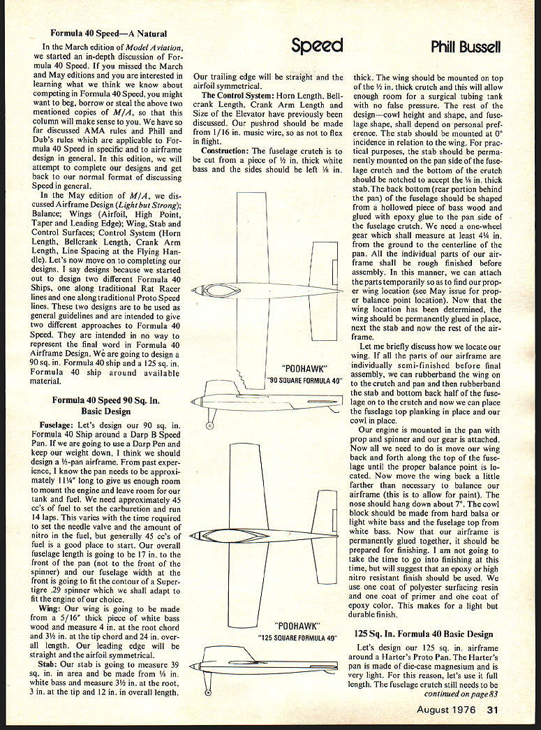
Formula 40 Speed 90 Sq. In. Basic Design
Fuselage: Let's design our 90 sq. in. Formula 40 Ship around a Darp Pan. If we are going to use a Darp Pan and keep our weight down, I think we should design a 1/2-pan airframe. From past experience, I know the pan needs to be approximately 11 1/4" long to give us enough room to mount the engine and leave room for our tank and fuel. We need approximately 45 cc's of fuel to set the carburetion and run 14 laps. This varies with the time required to set the needle valve and the amount of nitro in the fuel, but generally 45 cc's of fuel is a good place to start. Our overall fuselage length is going to be 17 in. to the front of the pan (not to the front of the spinner) and our fuselage width at the front is going to fit the contour of a Super Tigre .29 spinner which we shall adapt to fit the engine of our choice.
Wing: Our wing is going to be made from a 5/16" thick piece of white bass wood and measure 4" root chord and 3" tip chord and 24" overall length. Our leading edge will be straight and the airfoil symmetrical.
Stab: Our stab is going to measure 39 sq. in. in area and be made from 1/8" white bass and measure 3 1/2" at the root, 3" at the tip and 12" in overall length.
Our trailing edge will be straight and the airfoil symmetrical.
The Control System: Horn Length, Bellcrank Length, Crank Arm Length and Size of the Elevator have previously been discussed. Our pushrod should be made from 1/16" music wire, so as not to flex in flight.
Construction: The fuselage crutch is to be cut from a piece of 1/2" thick white bass and the sides should be left 1/8" thick. The wing should be mounted on top of the 1/2" thick crutch and this will allow enough room for a surgical tubing tank with no false pressure. The rest of the design—cowl height and shape, and fuselage shape, shall depend on personal preference. The stab should be mounted at 0° incidence in relation to the wing. For practical purposes, the stab should be permanently mounted on the pan side of the fuselage crutch and the bottom of the crutch should be notched to accept the 1/8" thick stab. The back bottom (rear portion behind the pan) of the fuselage should be shaped from a hollowed piece of bass wood and glued with epoxy glue to the pan side of the fuselage crutch. We need a one-wheel gear which shall measure at least 4 1/4" from the ground to the centerline of the pan. All the individual parts of our airframe shall be rough finished before assembly. In this manner, we can attach the parts temporarily so as to find our proper wing location (see May issue for proper balance point location). Now that the wing location has been determined, the wing should be permanently glued in place, next the stab and now the rest of the airframe.
Let me briefly discuss how we locate our wing. If all the parts of our airframe are individually semi-finished before final assembly, we can rubberband the wing on to the crutch and pan and then rubberband the stab and bottom back half of the fuselage on to the crutch and now we can place the fuselage top planking in place and our cowl in place.
Our engine is mounted in the pan with prop and spinner and our gear is attached. Now all we need to do is move our wing back and forth along the top of the fuselage until the proper balance point is located. Now move the wing back a little farther than necessary to balance our airframe (this is to allow for paint). The nose should hang down about 7°. The cowl block should be made from hard balsa or light white bass and the fuselage top from white bass. Now that our airframe is permanently glued together, it should be prepared for finishing. I am not going to take the time to go into finishing at this time, but will suggest that an epoxy or high nitro resistant finish should be used. We use one coat of polyester surfacing resin and one coat of primer and one coat of epoxy color. This makes for a light but durable finish.
125 Sq. In. Formula 40 Basic Design
Let's design our 125 sq. in. airframe around a Harter's Proto Pan. The Harter's pan is made of die-case magnesium and is very light. For this reason, let's use it full length. The fuselage crutch still needs to be made out of 1/2 in. thick bass and the overall length will be approximately 19 1/2 in. long. This is the approximate length of the Harter's pan after the pan is cut to match the diameter of the Supertigre 29 spinner and the engine is mounted. Let's make our wing from 3/8 in. thick hard (6 lb. and 8 lb.) "C" grain balsa. We can save a little weight over a bass wing and this is very important in a big airframe. The wing will be 25 in. long with a 6 in. root and a 4 in. tip chord. Use a 3/8 x 3 in. bass or maple spar to mount your control system and tie down bolts. Our wing leading edge is straight and all the wing taper is from the trailing edge. Our airfoil is symmetrical with a 30% high point.
Stab: Our stab is going to measure 39 sq. in. in area and should be made from 3/16 in. hard balsa. The root chord is 3 in. and the tip chord is 2 1/2 in. and the overall length is 13 in.
The rest of the design is very similar to construction techniques on any speed ship. The cowl height and shape depends on the engine used and personal preference. The fuselage top should be made from hard balsa and, again, our wing location is found as it was on our 90 sq. in. design by pre-assembling all the component parts of our airframe and moving the wing fore and aft until the C/G is located right on the line outlet. Allow about a 7° to 10° nose drop to allow for paint and then permanently attach the wing to the top of the crutch. When carving a wing always leave a flat section on the bottom wide enough to mount the wing to the crutch and when it comes time to permanently mount the wing to the top of the crutch, you don't have to measure wing alignment. You know your wing is mounted at 0° angle of attack. It is very important that your wing and stab are mounted at 0° angle of attack with the engine thrust line.
Finish: The finish on a big airframe is very important and care should be given or your bird will be oversprayed. After your airframe is assembled, finished, sanded and all bad spots puttied, I recommend that you cover all balsa parts with dope and tissue and then one coat of primer and one coat of epoxy color should give you a good light finish.
In our next column, we will discuss engines, props, fuel and limited rework procedures.
(My address is: 4803 Fallon Pl., Dallas, TX 75227.)
Transcribed from original scans by AI. Minor OCR errors may remain.

