
Control Line: Speed
Gene Hempel
Introduction
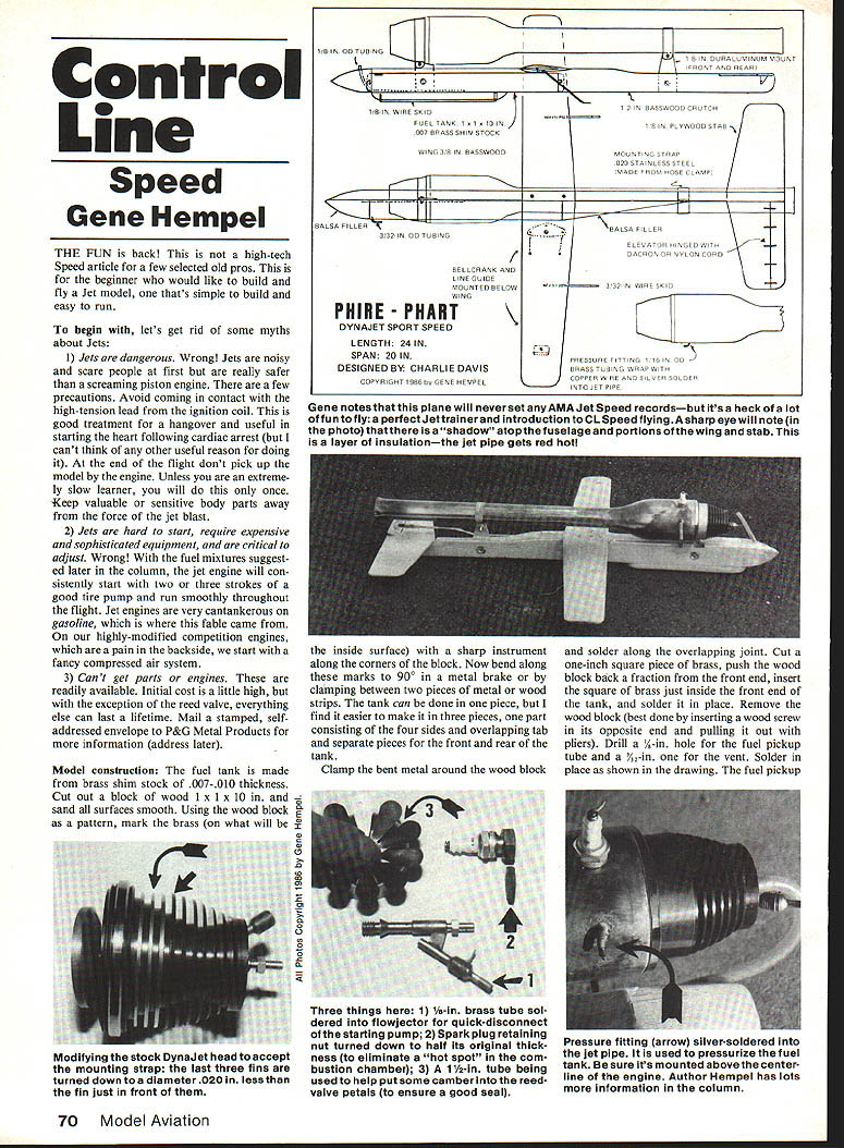
The fun is back! This is not a high-tech Speed article for a few selected old pros. This is for the beginner who would like to build and fly a jet model—one that's simple to build and easy to run.
To begin with, let's get rid of some myths about jets.
Myths about jets
- Jets are dangerous.
- Wrong. Jets are noisy and may scare people at first, but they are generally safer than a screaming piston engine. There are a few precautions: avoid contact with the high-tension lead from the ignition coil, and at the end of the flight don't pick up the model by the engine. Keep valuable or sensitive body parts away from the jet blast.
- Jets are hard to start, require expensive and sophisticated equipment, and are critical to adjust.
- Wrong. With the fuel mixtures suggested later, a jet engine will consistently start with two or three strokes of a good tire pump and run smoothly throughout the flight. Jet engines become cantankerous on gasoline, which caused this fable. Highly modified competition engines may need fancy compressed air systems, but stock engines are straightforward.
- Can't get parts or engines.
- Wrong. Parts and engines are readily available. Initial cost is a little high; however, except for the reed valve, everything else can last a lifetime. Mail a stamped, self-addressed envelope to P&G Metal Products for more information (address below).
Model construction
Fuel tank
- Make the tank from brass shim stock .007–.010 in. thick.
- Cut a wood block 1 × 1 × 10 in. and sand all surfaces smooth. Use the wood block as a pattern and mark the brass (on what will be the inside surface) along the corners of the block with a sharp instrument.
- Bend along these marks to 90° in a metal brake or by clamping between two pieces of metal or wood strips.
- The tank can be made in one piece, but it's easier in three parts: one piece for the four sides with an overlapping tab and separate pieces for the front and rear.
- Clamp the bent metal around the wood block and solder the overlapping joint.
- Cut a 1-in. square piece of brass, push the wood block back a fraction from the front end, insert the square inside the front end of the tank and solder it in place.
- Remove the wood block (best done by inserting a wood screw in its opposite end and pulling it out with pliers).
- Drill a 1/4-in. hole for the fuel pickup tube and a 3/32-in. vent. Solder in place as required. The fuel pickup tube should extend five inches back from the front of the tank.
- Cut another 1-in. square brass piece for the back end; it will fit just inside. Hold in place with masking tape and tack-solder the corners. Remove the tape and finish soldering.
- Small tabs soldered on the outboard side secure the tank to the fuselage crutch with wood screws.
Wing construction
- Use 3/16-in. basswood and make the wing symmetrical—do not use a lifting airfoil; that makes the jet extremely unstable.
- Cut out the wing blank, lay it on a flat surface, and draw lines along the leading and trailing edges halfway through the thickness.
- Calculate 40% (0.40) of the wing chord from the leading edge and mark a point at the wing tip and one at the root. Join these points with a solid line on both the top and bottom of the wing blank.
- Carve the airfoil using a wood rasp or razor plane, or use a one-inch belt sander for rough shaping and finish with sandpaper by hand.
- Prefer leaving the bottom of the center section uncarved to make attaching the wing to the fuselage easier; this requires only a notch in the crutch rather than matching the airfoil contour.
Fuselage crutch and engine mounting
- The fuselage crutch is 3/16-in. basswood.
- Cut front and rear engine supports from 1/8-in. duralumin (hard aluminum) and cut notches on the inboard side of the crutch so they sit flush.
- Mounting rings can be made from large hose clamps or .025-in. stainless steel. To lay out the ring, wrap masking tape around the engine where the mount will fit, cut out a 1/8-in. section of the tape, place it on the metal strip to transfer the exact curvature, and bend tabs in the metal beyond the tape ends.
- The mounting strap must be springy and will be hard to close when mounting the engine. To help, put a machine screw through holes in the tabs and, with the strap held circular, heat it with a torch or gas burner so it tends to retain shape after cooling.
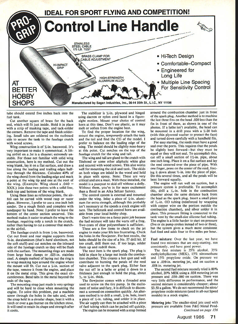
- The engine can be mounted with a strap around the combustion chamber just in front of the spark plug, or machine the last three fins on the head .020 in. less than the fin in front of them to provide a seat for the strap. If you don't have a lathe, mount the head in a drill press with a 1/4-20 bolt (use a thin plywood washer to protect the face) and careful hand filing.
Stabilizer and controls
- Make the stabilizer from 1/8-in. plywood and hinge it using dacron or nylon cord laced in a figure-eight motion. Mount your chosen control horn now. Do not use plastic for the control horn; it may melt or soften from engine heat.
- The control system is external and mounted under the wing. Inlay a piece of 1/8-in. aluminum for extra strength (probably not necessary for stock engine speeds). Bellcrank and control horn are available from hobby shops.
Finding the center of gravity and assembly
- To locate the proper wing position, mount the engine, temporarily attach the tank and tail, and find the C.G. I prefer to balance on the leading edge of the tail. The model should be slightly nose-heavy at this point.
- Cut notches on the top of the fuselage crutch for the wing and tail.
- Glue the wing and tail to the crutch with Titebond or another aliphatic white glue and secure with wood screws. This method also works for mounting the skid and tank.
- Skids should be mounted in the rear and held in place with epoxy.
- Note: With critical areas installed, the model is easy to skid off without a dolly; without them, expect much more excitement.
Finish
- Don't waste time on a fancy paint job; the fuel mixture will remove varnish. Two coats of clear polyurethane are sufficient.
Engine checks and preparation
Flow vector
- Check the holes in the flow vector. For best results, make the holes the size of a No. 5 drill bit. If too small, drill them out; if too large, solder them up and redrill.
Spark plug and combustion chamber
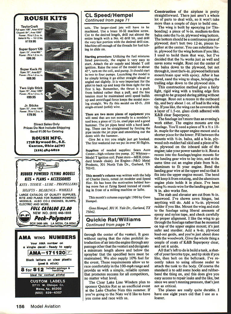
- The spark plug is often held in place by a large nut inside the combustion chamber; this creates a hot spot and can burn petals of the reed valve adjacent to the plug. Face the nut off in a lathe or grind it down to a thickness just enough to hold the plug (about 3/16 in.).
- The flow vector commonly comes with a threaded area for screwing on the primer bulb. In practice, a screwed-on connection is hard to disconnect quickly. Instead, drill a small 1/8-in. hole, insert a piece of 1/4-in. tubing, and solder it in place. The air supply can then be attached with fuel tubing and pulled off quickly.
Reeds and sealing
- For easy starting, the reed petals must seal evenly over the ports and be slightly bent forward.
- To bend them equally, cut a 1-in. length of 1/8-in. pipe, place the reed centered over the pipe on a flat surface, and press the center of the reed down about 1/32 in. into the pipe. Repeat several times so all petals bend forward equally.
Fuel feed: suction vs pressure
- The engine will run on suction, but a pressure system is preferable for more consistent fuel feed.
- To add pressure feed, drill a 1/8-in. hole in the combustion chamber about the same distance back from the head as the spark plug. Insert a small piece of 1/8-in. OD tubing (reinforce the portion outside the combustion chamber with copper wire) and silver-solder it in place.
- Connect a small piece of tubing from this fitting to the tank vent using small silicone fuel tubing. The engine is a bit harder to start on pressure (five or six pump strokes instead of two or three), but fuel delivery is more consistent.
Fuel mixtures and jetting
Over the last year we found two mixtures that are easy-starting, run consistently, and have good power.
- Mixture A
- 35% alcohol, 35% methyl ethyl ketone (MEK), 15% nitromethane, 15% propylene oxide.
- Metering jets: on pressure use .039-in.; on suction use .058-in.
- Mixture B (cheaper)
- 80% alcohol, 20% MEK.
- Metering jets: on pressure use .038-in.; on suction use .058–.060 in.
- Performance differences are small; the second mixture is considerably cheaper (about $3.50 per gallon). We do not recommend nitro/propylene oxide mixtures used in all-out Speed models in a stock engine.
Metering jets
- Smaller-sized jets used with pressure are available from P&G Metal Products.
- Larger-sized jets must be machined from a brass 10-32 machine screw: cut to desired length, drill out almost the entire length with a No. 42 drill bit, then drill the last portion with the desired drill size. Machine off enough of the threads for the jetting to slip on.
Starting and flying procedure
- Using the fuel mixtures above, the engine is easy to start. Attach the air supply and Model T coil ignition. Raise the nose of the model to about 45 degrees, turn on the coil, and pump. It should start in two to four pumps.
- Launch the model by letting it go straight ahead or angled out slightly. Back up and keep the lines tight for the first quarter lap. Remember that thrust is a push from behind rather than a pull, and line tension must be maintained until speed and centrifugal force keep the model moving straight.
- We fly this model on 65-ft .018 single-strand (solid) wire.
Tools and maintenance
- Two items not normally in a modeler's toolbox that you'll need: a piece of 1/8-in. steel pipe and a good hammer. Jet pipes bend; they can be straightened by forcing the steel pipe inside the jet pipe and smoothing dents with the hammer.
- With proper setup, you might get hooked—our first weekend with this model yielded over 30 flights.
Suppliers
- Sears Auto Center — high-volume tire pump
- JC Whitney — Model T ignition coil
- Paint store — MEK (standard brands)
- Jet engines and smaller jets — P&G Metal Products, 301 North Yale Dr., Garland, TX 75042
Acknowledgments and copyright
This column was written with the help of Charlie Davis, noted jet modeler and Speed flier. He motivated having more fun at flying Speed instead of standing in front of a milling machine or lathe.
This month's column copyright 1986 by Gene Hempel.
Gene Hempel 301 N. Yale Dr., Garland, TX 75042
Transcribed from original scans by AI. Minor OCR errors may remain.

